W-L-4031
July 28, 2009
July 28, 2009
F Ratings — 1 and 2 h (See Item 1)
T Rating — 1/4 h
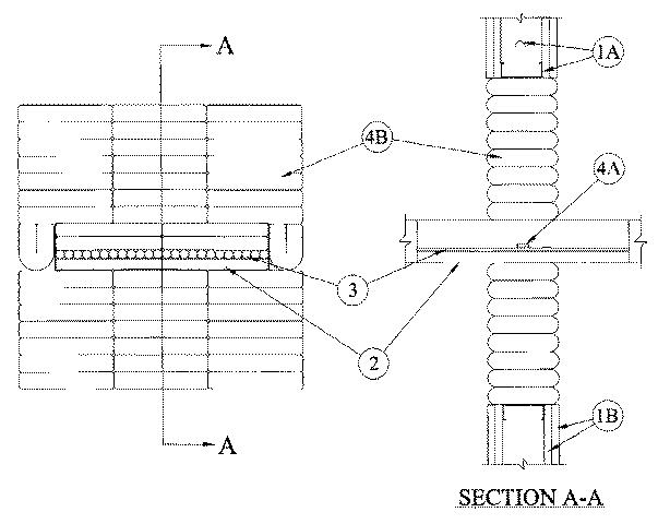
1.Wall Assembly — The 1 or 2 h fire-rated gypsum board/stud wall assembly shall be constructed of the materials and in the manner specified in the individual U300 or U400 Series Wall and Partition Designs in the ULC Fire Resistance Directory and shall include the following construction features:
A.Studs — Wall framing shall consist of either wood or steel channel studs. Wood studs to consist of nom 2 by 4 in. lumber spaced 16 in. OC. Steel studs to be min 3-1/2 in. wide and spaced max 24 in. OC. Additional framing members to be installed in stud cavity containing cable tray to form a rectangular box around the opening.• B.Gypsum Board — Min 5/8 in. thick, 4 ft wide with square or tapered edges. The gypsum board type, thickness, number of layers and orientation shall be as specified in the individual U300 or U400 Wall and Partition Design. If the cable tray is installed in a wood stud/gypsum board assembly, the max area of opening is 348 sq in. with max height of 24 in. and max width of 14-1/2 in. If the cable tray is installed in a steel stud/gypsum board assembly, the max area of opening is 576 sq in. with max dimension of 24 in.The hourly F Rating of the firestop system is equal to the hourly fire rating of the wall assembly in which it is installed.
• 2.Cable Tray — Max 18 in. wide by max 4 in. deep open-ladder cable tray with channel-shaped side rails formed of min 0.065 in. thick aluminum or steel with 1 in. wide rungs spaced 9 in. OC. One cable tray to be centered in opening. The annular space between the cable tray and periphery of opening shall be min 3 in. to max 10 in. Cable trays to be rigidly supported on both sides of wall assembly.
3.Cables — Aggregate cross-sectional area of cables in cable tray to be max 23 and 28 percent of the cross-sectional area of the cable tray based on a max 3 in. cable loading depth within the cable tray for aluminum and steel trays, respectively. Any combination of the following types and sizes of copper conductor cables may be used:
A.Max 25 pr No. 24 AWG telephone cables with polyvinyl chloride (PVC) insulation and jacket. B.Max 4 pr No. 24 AWG telephone cables with PVC insulation and jacket. C.Max 1/C - 500 kcmil (or smaller) cable with PVC insulation and jacket. D.Max 2/C with ground No. 12 AWG Type NM nonmetallic sheathed (Romex) cable with PVC insulation and jacket.
• 3A.Through Penetrating Product — (Not Shown) As an alternate to Item 3, through-penetrating products to be installed within the cable tray. Aggregate cross-sectional area of in through-penetrating products cable tray to be max 23 and 28 percent of the cross-sectional area of the cable tray based on a max 3 in. cable loading depth within the cable tray. Any combination of the following types and sizes of through-penetrating products may be used:
A.Two or more twisted copper conductors No. 6 AWG (or smaller) Power Limited Circuit Cable with or without a jacket under a metal armor.
RECTORSEAL B.Two or more twisted copper conductors No. 10 AWG (or smaller) Power Limited Fire Alarm Cable with or without a jacket under a metal armor.
RECTORSEAL C.Two or more twisted copper conductors No. 12 AWG (or smaller) Non Power Limited Fire Alarm Cable with or without a jacket under a metal armor.
RECTORSEAL D.Max two conductors with ground No. 12 AWG Metal-Clad Cable.
RECTORSEAL
4.Firestop System — The Firestop system shall consist of the following:
• A.Fill, Void or Cavity Materials—Caulk — Nom 1/4 in. thick by 1 in. wide strip of caulk applied over both surfaces of cable bundle and overlapping into inside rails of cable tray approx 1/2 in. Caulk strip centered within annular space.
RECTORSEAL — Metacaulk 1000• B.Fill, Void or Cavity Material—Pillows — Max 9 in. long by 6 in. wide by 2 in. thick plastic covered intumescent pillows tightly packed into opening. Pillows tightly packed to fill the annular space between cable tray and periphery of opening. Pillows installed with 6 in. dimension projecting through wall and centered within the opening.
RECTORSEAL — Metacaulk Pillows• C.Fill, Void or Cavity Materials—Caulk — (Not Shown) - After installation of the pillows, min 1/4 in. depth of caulk shall be applied to seal any voids between cables, between cables and the pillows, and between cable tray and pillows on both sides of the wall assembly.
RECTORSEAL — Metacaulk 1000