F-C-2449
August 29, 2016
August 29, 2016
F Rating — 1 Hr
FT Rating — 1 Hr
FH Rating — 0 and 1 Hr (See Items 2 and 3)
FTH Rating — 0 and 1 Hr (See Items 2 and 3)
- System tested with a pressure differential of 50 Pa between the exposed and the unexposed surfaces with the higher pressure on the exposed side.
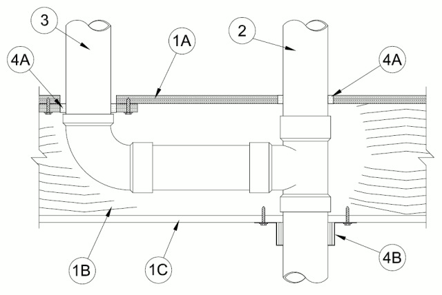
1.Floor Assembly — The 1 hr fire rated wood truss or combination wood and steel truss Floor-Ceiling assembly shall be constructed of the materials and in the manner described in the individual L500 Series Design in the UL Fire Resistance Directory, as summarized below:
A.Flooring System — Lumber or plywood subfloor with finish floor of lumber, plywood or Floor Topping Mixture* as specified in the individual Floor-Ceiling Design. Diam of opening in subfloor and subfloor patch (see Item 3) shall be 1/2 in. (13 mm) larger than the outside diam of nonmetallic pipe (Items 2 and 3).B.Joists — Nom 10 in. (254 mm) deep (or deeper) lumber, steel or combination lumber and steel joists, trusses or Structural Wood Members* with bridging as required and with ends firestopped.C.Gypsum Board* — Nom 4 ft (1.2 m) wide by 5/8 in. (16 mm) thick, attached as described in the individual Floor-Ceiling Design.
2.Through Penetrant — One nonmetallic pipe to be installed within the firestop system. Pipe to be rigidly supported on both sides of floor-ceiling assembly. The annular space between pipe and periphery of opening shall be min 0 in. (point contact) to max 1/2 in. (13 mm). The following types and sizes of nonmetallic pipes may be used:
A.Polyvinyl Chloride (PVC) Pipe — Nom 4 in. (102 mm) diam (or smaller) Schedule 40 solid core or cellular core PVC pipe for use in closed (process or supply) or vented (drain, waste or vent) piping system.B.Chlorinated Polyvinyl Chloride (CPVC) Pipe — Nom 4 in. (102 mm) diam (or smaller) SDR 13.5 CPVC pipe for use in closed (process or supply) or vented (drain, waste or vent) piping systems.C.Acrylonitrile Butadiene Styrene (ABS) Pipe — Nom 4 in. (102 mm) diam (or smaller) Schedule 40 solid core or cellular core ABS pipe for use in closed (process or supply) or vented (drain, waste or vent) piping system.The hourly FH and FTH Ratings of the firestop system are equal to 0 hr for ABS penetrants (Item 2C) and 1 hr for PVC and CPVC penetrants (Items 2A and 2B).
3.Branch Piping — (Optional) — One nonmetallic pipe to be connected to through penetrant (Item 3) and installed within opening in subfloor patch. To accommodate branch piping, max 8 by 10 in. (203 mm by 254 mm) opening cut into subfloor and patched with rectangular piece of plywood of same type and thickness as subfloor. Plywood patch to overlap min 1 in. (25 mm) around periphery of cutout and to be secured to subfloor with 1-1/2 in. (38 mm) long steel screws with one at each corner and spaced max 4 in. (102 mm) OC along each overlapping edge. The annular space between branch pipe and periphery of opening within patch shall be min 0 in. (point contact) to max 1/2 in. (13 mm). The following types and sizes of nonmetallic pipes may be used:
A.Polyvinyl Chloride (PVC) Pipe — Nom 4 in. (102 mm) diam (or smaller) Schedule 40 solid core or cellular core PVC pipe for use in closed (process or supply) or vented (drain, waste or vent) piping system.B.Chlorinated Polyvinyl Chloride (CPVC) Pipe — Nom 4 in. (102 mm) diam (or smaller) SDR 13.5 CPVC pipe for use in closed (process or supply) or vented (drain, waste or vent) piping systems.C.Acrylonitrile Butadiene Styrene (ABS) Pipe — Nom 4 in. (102 mm) diam (or smaller) Schedule 40 solid core or cellular core ABS pipe for use in closed (process or supply) or vented (drain, waste or vent) piping system.The hourly FH and FTH Ratings of the firestop system are equal to 0 hr for ABS penetrants (Item 3C) and 1 hr for PVC and CPVC penetrants (Items 3A and 3B).
4.Firestop System — The firestop system shall consist of the following:
A.Fill, Void or Cavity Material* — Min 3/4 in. (19 mm) thickness of fill material applied within annular space around perimeter of through penetrant (Item 2), flush with top surface of floor. Min 3/4 in. (19 mm) thickness of fill material applied within annular space around perimeter of branch piping (Item 3) flush with top surface of plywood floor patch. Min 1/2 in. (13 mm) diam bead applied at the pipe/floor interface and the pipe/plate interface.
RECTORSEAL — Metacaulk MC 150+, Metacaulk 1000, Metacaulk 350i, Biostop 500+, Biostop 150+, Biostop 350iB.Firestop Device* — Galv steel collar lined with an intumescent material sized to fit outer diam of the through penetrant (Item 2). Device to be installed around through penetrant at bottom of floor in accordance with accompanying installation instructions. Device incorporates anchor tabs for securement to both surfaces of the wall by means of min 3/16 in. (5 mm) diam steel hollow wall anchors.
RECTORSEAL — Metacaulk Pipe Collar, Biostop Pipe Collar or Flamesafe Pipe CollarB1.Fill, Void or Cavity Material* — Wrap Strip — As an alternate to Item 4B, three layers of nom 1/4 in. (6 mm) thick by 1 in. (25 mm) wide intumescent wrap strip wrapped around the outer circumference of the pipe flush with bottom of floor. Wrap strip installed with offset butted seams and temporarily secured with tape or tie wire.
RECTORSEAL — Metacaulk Wrap Strip, Biostop Wrap Strip or Flamesafe Wrap StripB2.Steel Collar — When Item 4B1 is used, a collar fabricated from coils of precut min 0.016 in. thick (0.41 mm) galv steel available from fill material manufacturer shall be installed to retain wrap strip. Collar shall be nom 1 in. (25 mm) deep with 1 in. (25 mm) wide by 1-1/2 in. (38 mm) long anchor tabs for attachment to wall. In addition, collar provided with 1/2 in. (13 mm) wide by 3/4 in. (19 mm) long retainer tabs opposite the anchor tabs. Collar shall be wrapped over the wrap strip, overlapping min 1 in. (25 mm). The retainer tabs are folded 90 deg towards the pipe to maintain the annular space around the pipe and to retain the wrap strip. Collars secured to gypsum ceiling at each anchor tab with Type G laminating screws or 3/16 in. (5 mm) diam steel hollow wall anchors in conjunction with 1/4 by 5/8 in. (6 by 16 mm) diam steel washers.