June 25, 2021
June 25, 2021
|
ANSI/UL 1479 (ASTM E814) |
CAN/ULC S115 |
|
F Rating - 2 Hr |
F Rating - 2 Hr |
|
T Rating – 1 Hr |
FT Rating – 1 |
|
L Rating at Ambient - Less Than 1 CFM/device |
FH Rating - 2 Hr |
|
L Rating at 400°F - Less Than 1 CFM/device |
FTH Rating - 1Hr |
|
W Rating – Class 1 (see item 2) |
L Rating at Ambient - Less Than 5.1 L/s/device |
|
|
L Rating at 204°C - Less Than 5.1 L/s/device |
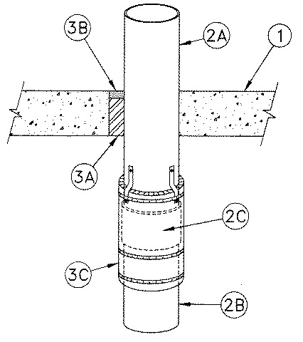
1. Floor Assembly — Min 2-1/2 in. (64 mm) thick reinforced light weight or normal weight (100-150 pcf or 1600-2400 kg/m3) concrete. Floor may also be constructed of any min 6 in (152 mm) thick UL Classified hollow-core Precast Concrete Units*. Max diam of opening is 7 in. (178 mm).
1A. Floor Assembly — As an alternate to item 1. The fire rated unprotected concrete and steel deck assembly shall be constructed of the materials and in the manner specified in the individual D900 Series designs in the UL Fire Resistance Directory and as summarized below:
A. Concrete — Min 2-1/2 in. (64 mm) thick reinforced lightweight or normal weight (100-150 pcf or 1600-2400 kg/m3) concrete.
B. Steel Floor and Form Units* — Composite or non-composite max 3-in (76 mm) deep fluted galv units as specified in the individual Floor-Ceiling design.
2. Through-Penetrant — One metallic pipe, conduit or tubing installed either concentrically or eccentrically within the firestop system. The annular space between penetrant and periphery of opening shall be min of 0 in. (point contact) to max 1-7/8 in. (48 mm). When W Rating applies, the annular space shall be min ¼ in. (6 mm) to max 1-3/4 in. (44 mm). Penetrant to be rigidly supported on both sides of floor assembly, and terminate a minimum 6 in. (152 mm) below the bottom surface of floor assembly
2A. Metallic Pipe — Nom 6 in. (152 mm) diam (or smaller), Schedule 10 (or heavier) steel pipe or cast/ductile iron pipe installed concentrically or eccentrically within the firestop system.
2B. Non-Metallic Pipe — Nom 6 in. (152 mm) diam (or smaller), Schedule 40, cellular or solid core polyvinyl chloride (PVC) pipe, installed on bottom end of metallic pipe (Item 2A), for use in vented (drain, waste, or vent) piping systems. Pipe to be rigidly supported.
2C. Compression Coupling — Nom 6 in. (152mm) diam (or smaller) compression type pipe coupling joining metallic pipe (Item 2A) and non-metallic pipe (Item 2B). Coupling to overlap each pipe by a min 2 in. (102 mm) and to be properly secured to pipes.
3. Firestop System — The firestop system shall consist of the following:
A. Packing Material — Min 2 in. (51 mm) thickness of min 4 pcf (64 kg/m3) mineral wool batt insulation firmly packed into opening as a permanent form. Packing material to be recessed from top surface of floor to accommodate the required thickness of fill material.
B. Fill, Void or Cavity Material* - Sealant — Min 1/2 in. (13 mm) thickness of fill material applied within the annulus, flush with top surface of floor.
C. Firestop Device* — Galv steel sleeve lined with an intumescent material, sized to fit the specific diameter of the pipes and coupling. Device to be wrapped around the pipes/coupling connection with a min 2-1/2 in. (63 mm) overlap to the metallic pipe (Item 2A) and min 3-1/2 in. (89 mm) overlap to the non-metallic pipe (Item 2B). The devices shall be secured to the metallic pipe, non-metallic pipe and coupling with three stainless steel hose clamps of min 1/2 in. (13 mm) width and 0.028 in. (0.71 mm) thickness centered on the length of the sleeve and min 1 in. (25 mm) from each edge of the sleeve. A fourth hose clamp is to be secured around metallic pipe such that a minimum of three 1-in. (25mm) wide 24 gauge (0.6 mm) metal tabs loop around the top hose clamp on the sleeve and the clamp around the metallic pipe to further secure sleeve.