September 16, 2010
F Rating — 2 Hr
T Rating — 0 Hr
L Rating At Ambient — 7 CFM
L Rating At 400 F — 7.3 CFM
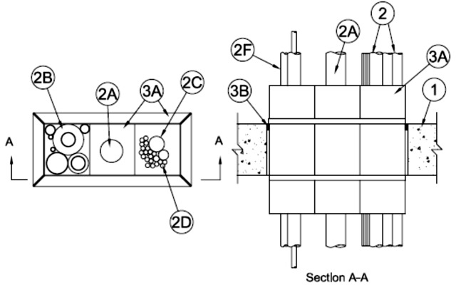
1.Floor or Wall Assembly — Min 2-1/2 in. (64 mm) thick reinforced lightweight or normal weight (100-150 pcf or 1600-2400 kg/m3) concrete. Wall may also be constructed of any UL Classified Concrete Blocks*. Max area of opening is 56 1/4 in.2 (363 cm2) with a max dimension of 12 1/2 in. (318 mm) for square devices. Max diam of opening is 4-1/2 in. (114 mm) for round devices.
See Concrete Blocks (CAZT) category in Fire Resistance Directory for names of manufacturers.
2.Through-Penetrants — One or more metallic pipes, conduits or tubes, nonmetallic pipes, conduits or tubes, cables, and combinations of penetrants, as described below, may be installed within each firestop device (Item 3A) as further specified below. Through penetrants to be rigidly supported on both sides of wall assembly. The following types and sizes of through-penetrants may be used:
A.Metallic Penetrants — One or more metallic pipe, tubing or conduit may be installed concentrically or eccentrically within each firestop device (Item 3A). If multiple through penetrants are installed within the firestop device, a min 1/4 in. (6 mm) annular space is required between the through penetrants. Through penetrants to be rigidly supported on both sides of floor or wall assembly. The following types and sizes of through penetrants may be used:
A1.Steel Pipe — Nom 3 in. (76 mm) diam (or smaller) Schedule 10 (or heavier) steel pipe.A2.Iron Pipe — Nom 3 in. (76 mm) diam (or smaller) cast or ductile iron pipe.A3.Copper Tubing — Nom 3 in. (76 mm) diam (or smaller) Type L (or heavier) copper tube.A4.Copper Pipe — Nom 3 in. (76 mm) diam (or smaller) Regular (or heavier) copper pipe.B.Tube Insulation - Plastic+ — Nom 1/2 in (13 mm) thick or smaller) acrylonitrile butadiene/polyvinyl chloride (AB/PVC) flexible foam furnished in the form of tubing with skin may be used on the copper tubes. If multiple insulated through penetrants are installed within the firestop device, the insulated through penetrants may be bundled together. If tube insulation is used, the max nom diam if the metallic through penetrant shall be 3/4 in. (19 mm).
See Plastics+ (QMFZ2) category in the Plastics Recognized Component Directory for names of manufacturers. Any Recognized Component tube insulation material meeting the above specifications and having a UL 94 Flammability Classification of 94-5VA may be used.
C.Nonmetallic Penetrants — One or more nonmetallic pipes or tubes, as described in a single line item below, may be installed within each firestop device (Item 3A):
C1.Polyvinyl Chloride (PVC) Pipe — One nom 1 in. (25 mm) diam (or smaller) Schedule 40 solid core PVC pipe for use in closed (process or supply) or vented (drain, waste or vent) piping systems.C2.Chlorinated Polyvinyl Chloride (CPVC) Pipe — One nom 1 in. (25 mm) diam (or smaller) SDR11 CPVC pipe for use in closed (process or supply) piping systems.C3.Rigid Nonmetallic Conduit+ — One nom 1 in. (51 mm) diam (or smaller) Schedule 40 PVC conduit installed in accordance with Article 352 of the National Electrical Code (NFPA No. 70).See Rigid Nonmetallic, Schedule 40 and 80 PVC Conduit (DZYR) category in the Electrical Construction Equipment Directory for names of manufacturers.
C4.Electrical Nonmetallic Tubing (ENT)+ — One nom 1 in. (25 mm) diam (or smaller) ENT installed in accordance with Article 362 of the National Electrical Code (NFPA No. 70).See Electrical Nonmetallic Tubing (FKHU) category in the Electrical Construction Equipment Directory for names of manufacturers.
C5.Optical Fiber/Communications/Signaling/Coaxial Cable Raceways+ — One nom 1 in. (25 mm) diam (or smaller) plenum rated raceways installed in accordance with the National Electrical Code (NFPA No. 70).D.Cables — One or more cables concentrically or eccentrically within each firestop device. Cables installed in a bundle having max bundle diam of 2 1/2 in. (64 mm). Any combination of the following types and sizes of cables may be used:
D1.Max 2/C No. 18 AWG copper conductor thermostat cable with polyvinyl chloride (PVC) insulation and jacket materials. D2.Max 4 pair No. 24 AWG copper conductor Cat5e or Cat 6 telephone cable with PVC insulation and jacket materials. D3.Max RG/U (or smaller) coaxial cable with foam high density polyethylene insulation and PVC jacket materials. D4.Max 3/C (with ground) No. 14 AWG (or smaller) nonmetallic sheathed (Romex) cable with PVC insulation and jacket materials. D5.Max 1/C No. 8 AWG copper conductor cable with PVC insulation and nylon jacket materials. D6.Max 12 core No. 26 AWG shielded multi coax cable with foam high density polyethylene insulation and PVC jacket. D7.Max 48MM62.5 micron fiber optic cables with having a min FT-6 rating. D8.Max 62.5/125 micron fiber optic cables with having a min Riser rating. D9.Max 1/C 3/0 AWG copper conductor cable with PVC insulation and jacket materials. D10.Max three copper conductors (with ground) No. 12 AWG Metal Clad Cable+. D11.Max four copper conductors No. 2 AWG Metal Clad Cable+.
AFC CABLE SYSTEMS INC D12.Max 1/C 2/0 AWG non halogen copper conductor cable. D13.Max 300 pair No. 24 AWG copper conductor telephone cable with PVC insulation and jacket materials. D14.Max 30 pair No. 22 copper conductor shielded switchboard cable with PVC insulation and jacket materials. D15.Max RG/6 (or smaller) coaxial cable with fluorinated ethylene (FE) or PVC insulation and jacket materials. D16.Max RG/U (or smaller) coaxial cable with fluorinated ethylene (FE) or PVC insulation and jacket materials. D17.Max 7/C No. 12 AWG copper conductors with PVC insulation and jacket materials. D18.Max 4 pair No. 23 AWG copper conductor Cat 6 telephone cable with PVC insulation and jacket materials. D19.Max three copper conductors (with ground) No. 12 AWG steel Armored Cable+. D20.Max 04-02 2 5M fiber optic cables having a max diameter of 0.450 in. (11.4 mm). D21.Max 1/C No. 750 kcmil copper conductors with PVC insulation and fabric jacket materials. D22.Max 3/C with ground No. 2/0 AWG aluminum conductor SER cable with cross linked polyethylene (XLPE) insulation and PVC jacket.
3.Firestop System — The firestop system shall consist of the following:
A.Firestop Device* — A max of three square firestop devices may be ganged together. As an alternate, one round device may be centered within a round opening. Each device consists of a nom 2-1/2 by 2-1/2 by 10 in. (64 by 64 by 254 mm), a nom 4 by 4 by 10 in. (102 by 102 by 254 mm), a nom 2 in. (51 mm) diam by 10 in. (254 mm) or a nom 4 in. (102 mm) diam by 10 in. (254 mm) powder coated steel transit incorporating internal intumescent material, foam plugs and mounting flanges. Firestop device to be centered within opening and installed with ends projecting an equal distance beyond each surface of the floor or wall assembly in accordance with the accompanying installation instructions. The annular space between the firestop device(s) and the periphery of the opening shall be nom 1/4 in. (6 mm). Firestop devices secured in place by means of fill material (Item 4B) and steel split mounting flanges sized to accommodate the firestop device. Steel split mounting flanges installed on both sides of floor or wall after installation of fill material and secured to together with supplied steel set screws. Nom 1-1/2 in. (38 mm) thick pre-cut foam plugs sized to accommodate the through penetrant(s) and installed flush with each end of device on both sides of floor or wall assembly.
RECTORSEAL — Metacaulk® 4" square Pass Through Device, Metacaulk® 4" round Pass Through DeviceB.Fill, Void or Cavity Materials* - Caulk or Putty — Min1 in. (25 mm) thickness of fill material applied within the annulus, flush with top surface of floor or with both surfaces of wall. An additional bead of caulk shall be placed between ganged devices on both sides of floor or wall when multiple devices are used.
RECTORSEAL — Metacaulk 1000 or Metacaulk Fire Rated Putty.
+ Bearing the UL Listing Mark
# Bearing the UL Recognized Component Marking