W-L-8060
February 2, 2005
February 2, 2005
F Ratings — 1 and 2 Hr (See Item 1)
T Ratings — 1 and 1-1/4 Hr (See Item 1)
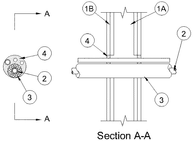
1.Wall Assembly — The 1 or 2 hr fire-rated gypsum board/stud wall assembly shall be constructed of the materials and in the manner specified in the individual U300, U400 or V400 Series Wall or Partition Designs in the UL Fire Resistance Directory and shall include the following construction features:
A.Studs — Wall framing may consist of either wood studs or steel channel studs. Wood studs to consist of nom 2 by 4 in. (51 by 102 mm) lumber spaced 16 in. (406 mm) OC. Steel channel studs to be min 3-1/2 in. (89 mm) wide and spaced max 24 in. (610 mm) OC.B.Gypsum Board* — Nom 5/8 in. (16 mm) thick, 4 ft. (1.2 m) wide with square or tapered edges. The gypsum board type, number of layers, fastener type and sheet orientation shall be as specified in the individual Wall and Partition Design. Max diam of opening is 4 in. (102 mm).The hourly F Rating of the firestop system is equal to the hourly fire rating of the wall assembly. The hourly T Rating is 1 hr and 1-1/4 hr for 1 and 2 hr rated assemblies, respectively.
2.Metallic Penetrants — A max of two pipes or tubes installed eccentrically or concentrically within the opening. Annular space between penetrants and periphery of opening to be min 0 in. (point contact) to max 1 7/8 in. (48 mm). Separation between penetrants to be min 0 in. (point contact) to max 1/2 in. (13 mm). Penetrants to be rigidly supported on both sides of the wall. The following types and sizes of penetrants may be used:
A.Copper Tubing — Nom 1 in. (25 mm) diam (or smaller) Type L (or heavier) copper tubing.B.Copper Pipe — Nom 1 in. (25 mm) diam (or smaller) Regular (or heavier) copper pipe.C.Steel Pipe — Nom 1 in. (25 mm) (or smaller) Schedule 5 (or heavier) steel pipe.D.Iron Pipe — Nom 1 in. (25 mm) (or smaller) cast or ductile iron pipe.
3.Cables — Max of two cable lengths installed eccentrically or concentrically within the opening. Annular space between penetrants and periphery of opening to be min 0 in. (point contact) to max 1 7/8 in. (48 mm). Separation between penetrants to be min 0 in. (point contact) to max 1/2 in. (13 mm). Penetrants to be rigidly supported on both sides of the wall. The following types and sizes of penetrants may be used:
A.Cables — Max 8/C No. 12 AWG multiconductor power and control cable with XLPE or PVC insulation and PVC jacket.
4.Tube Insulation-Plastics+ — Nom 3/4 in. (19 mm) thick (or less) acrylonitrile butadiene/polyvinyl chloride (AB/PVC) flexible foam furnished in the form of tubing. The tube insulation may be installed on a max of one pipe or tube. Annular space between the tube insulation and periphery of opening to be min 0 in. (point contact) to max 1-1/4 in. (32 mm). Space between insulated and uninsulated penetrants to be 0 in. (point contact) to max 1/4 in. (6 mm).
See Plastics (QMFZ2) category in the Plastics Recognized Component Directory for names of manufacturers. Any Recognized Component tube insulation material meeting the above specifications and having a UL 94 Flammability Classification of 94-5A may be used.
5.Fill, Void or Cavity Materials* - Caulk — Min 5/8 in. (16 mm) thickness of caulk applied within annulus, flush with both surfaces of wall assembly.
RECTORSEAL — MC 150+