W-L-8042
January 31, 2017
January 31, 2017
| ANSI/UL1479 (ASTM E814) | CAN/ULC S115 |
|---|---|

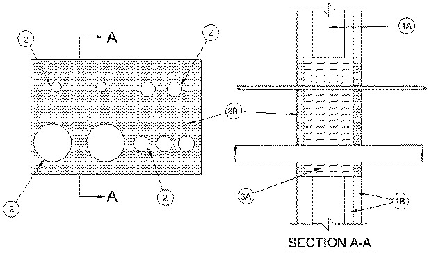
1.Wall Assembly — The 1 or 2 hr fire-rated gypsum board/stud wall assembly shall be constructed of the materials and in the manner specified in the individual U300, U400, V400 or W400 Series Wall and Partition Designs in the UL Fire Resistance Directory and shall include the following construction features:
A.Studs — Wall framing shall consist of either wood or steel channel studs. Wood studs to consist of nom 2 by 4 in. (51 by 102 mm) lumber spaced 16 in. (406 mm) OC. Steel studs to be min 3-1/2 in. (89 mm) deep and spaced max 24 in. (610 mm) OC. Framing of the opening shall consist of steel channel studs.B.Gypsum Board * — The gypsum board type, thickness, number of layers and orientation shall be as specified in the individual Wall and Partition Design. Max area of opening is 200 sq in. (1290 cm2) with a max dimension of 20 in. (508 mm).
The hourly F and FH Ratings of the firestop system are equal to the hourly fire rating of the wall assembly in which it is installed.
1A.Steel Sleeve — (Optional, not shown) - Max 16 in. (406 mm) by 6 in. (102 mm) 24 gauge (or heavier) galvanized steel with min 1 in. (25 mm) flanges. Sleeve to be installed flush with both surfaces of wall and secured to both sides of wall through the flanges with min 1/4 in. (6 mm) diam steel hollow wall anchors in conjunction with steel washers spaced a max 6 in. (152 mm) OC.When steel sleeve is used, T, FT and FTH Ratings are 0 hr.
2.Through Penetrants — Any combination of the following metallic penetrants to be installed within the firestop system. The annular space between penetrants shall be min 1/4 in. (6 mm) to max 3-1/2 in.(89 mm) and between penetrants and periphery of opening shall be min 1/4 in. (6 mm) to max 2-1/2 in. (64 mm). Penetrants to be rigidly supported on both sides of floor or wall assembly. The following types and sizes of EMT, metal clad cable or conduits may be used:
A.Conduit — Nom 4 in. (102 mm) diam (or smaller) electrical metallic tubing. Max two 4 in. (102 mm) diam conduits and max three 2 in. (102 mm) diam conduits per opening. When 3 or 4 in. (76 or 102 mm) diam EMT is used, T, FT and FTH Ratings are 1/2 hr. When 2 in. (51 mm) diam (or smaller) EMT is used, T, FT and FTH Ratings are 3/4 hr.B.Metal Clad Cable+ — Nom 2 in. (51 mm) diam (or smaller) 4 conductor 2/0 AWG steel or aluminum Metal Clad Cable+ with or without PVC jacket. Max two metal clad cables per opening. When metal clad cable is used, T, FT and FTH Ratings are 1/2 hr.See Through-Penetrating Products (XLHY) category in Vol. 2 of the Fire Resistance Directory for names of manufacturers.
C.Flexible Metal Conduit — Nom 1-1/2 in. (38 mm) diam (or smaller) steel or aluminum Flexible Metal Conduit±. Max two flexible metal conduits per opening. When flexible metal conduit is used, T, FT and FTH Ratings are 1/4 hr.See Flexible Metal Conduit (DXUZ) category in the Electrical Construction Materials Directory for names of manufacturers.
3.Firestop System — The firestop system shall consist of the following:
A.Packing Material — For 1 or 2 hr fire rated walls, min 3-1/2 in. (89 mm) or 4-3/4 in. (121 mm) thickness, respectively, of min 4 pcf (64 kg/m3) mineral wool batt insulation firmly packed into opening as a permanent form. Packing material to be recessed from both surfaces of wall to accommodate the required thickness of fill material.B.Fill, Void or Cavity Material* - Caulk — Min 5/8 in. (16 mm) thickness of fill material applied within the annulus, flush with both surfaces of wall.
RECTORSEAL — Metacaulk 1000