W-L-7294
June 13, 2019
June 13, 2019
| ANSI/UL1479 (ASTM E814) | CAN/ULC S115 |
|---|---|
1.Wall Assembly — The 1 or 2 hr fire rated framed gypsum board wall assembly shall be constructed of the materials and in the manner specified in the individual U400, V400 or W400 Series Wall and Partition Designs in the UL Fire Resistance Directory and shall include the following construction features:
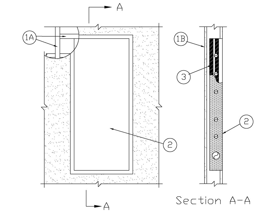
A.Studs — Wall framing shall consist of steel channel studs. Steel studs to be min 6 in. (152 mm) wide and spaced max 24 in. (610 mm) OC. Additional studs installed horizontally above and below the steel box (Item 2) for attachment of the steel box.B.Gypsum Board* — The gypsum board type, thickness, number of layers and orientation shall be as specified in the individual Wall and Partition Design. Size of cutout made to accommodate steel box (Item 2) is to be centered within the stud cavity and is to be max 1/2 in. (13 mm) wider and 1/2 in. (13 mm) higher than the width and height of the steel box such that the annular space between box and cut edge of gypsum is max 1/4 in. (13 mm) at sides and top and bottom of opening.The hourly Ratings are equal to the hourly rating of the wall assembly.
2.Steel Box — Min 18 gauge steel, Max 15 in. (381 mm) wide by max 36 in. (914 mm) high by max 6 in. (152 mm) deep medical gas valve box with a steel door and mounting flange. Box is to be installed flush with one side of wall and provided with min 1 in. (25 mm) by 18 gauge steel mounting flange (trim) overlapping gypsum board around periphery of opening. Steel box secured to horizontal framing members above and below the box with steel fasteners after application of Fill, Void or Cavity material (Item 3) on exterior surfaces of steel box. Each vertical side of steel box to be penetrated by min seven of any combination max 2 in. (51 mm) diam steel pipe, iron pipe, copper pipe or tube, steel conduit or EMT conduit. A max of 1 penetrant may be a max 3 in. steel conduit or EMT conduit.
3.Fill, Void or Cavity Materials* - Joint Strip — Nom. 1/16 in. (1.5 mm) thick strip of intumescent material faced on one side with an adhesive backing. For 15 in. wide boxes, adhere two 1 in. (25 mm) wide pieces of intumescent material flush with the each back edge of the box for the entire length of the box, and one 12 in. (305 mm) wide piece of intumescent material centered on the outer back surface of the box cut to the length of the box. For boxes less than 15 in. wide, the intumescent material should be evenly spaced and cover at least 90% of the width of the box and shall be cut to the length of the box. An additional two 2 in. (51 mm) wide pieces of intumescent material shall be adhered to the vertical sides of the box evenly spaced and running the entire length of the box. The two vertical sides and back side of the box shall be completely covered with FSK tape, and circular openings can be made to accommodate each penetrant. FSK Tape shall overlap the top and bottom of the box a min. 1/2 in. (13 mm).
RECTORSEAL —Metacaulk Firestop Joint Strip
4.Fill, Void or Cavity Material*— Sealant or Putty — (Not Shown) - Min 1/2 in. (13 mm) depth of sealant or putty shall be applied within the open ends of the conduits which terminate within the box.
RECTORSEAL —Metacaulk 150+, Metacaulk 350i, Metacaulk 1000, Metacaulk Fire Rated Putty
5.Insulation* — (Not Shown) - The entire wall stud cavity with the steel box (Item 2) and the immediately adjacent stud cavity to each side shall be fully insulated with min R13 glass fiber batt insulation or mineral wool insulation. Additional pieces of insulation shall be installed as needed to completely fill the voids around the steel box and any penetrants to the full depth of the stud cavity. Any glass fiber or mineral wool batt material bearing the UL Classification Marking as to Fire Resistance may be used.See Batts and Blankets* (BZJZ) Category or Forming Materials* (XHKU) Category for names of Classified companies.