W-L-7093
February 25, 2003
February 25, 2003
F Ratings — 1 and 2 Hr (See Item 1)
T Ratings — 0 and 3/4 Hr (See Item 1)
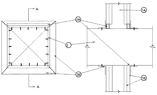
1.Wall Assembly — The 1 or 2 hr fire-rated gypsum board/steel stud wall assembly shall be constructed of the materials and in the manner described in the individual U400 Series Wall or Partition Design in the UL Fire Resistance Directory and shall include the following construction features:
A.Studs — Wall framing shall consist of min 3-1/2 in. wide steel channel studs spaced max 24 in. OC. Additional 3-1/2 in. wide steel studs shall be used to completely frame the opening.B.Gypsum Board* — 5/8 in. thick, 4 ft wide with square or tapered edges. The gypsum board type, thickness, number of layers, fastener type and sheet orientation shall be as specified in the individual U400 Series Design in the UL Fire Resistance Directory. Max area of opening is 552-1/4 sq in. with a max dimension of 23-1/2 in.The hourly F Rating of the firestop system is equal to the hourly fire rating of the wall assembly in which it is installed. The T Ratings for the firestop system are 0 hr and 3/4 hr when installed in 1 and 2 hr rated walls, respectively.
2.Steel Duct — Nom 23 in. by 23 in. (or smaller) No. 24 gauge (or heavier) galv steel duct to be installed either concentrically or eccentrically within the firestop system. The space between the steel duct and periphery of opening shall be min 0 in. (point contact) to max 1/2 in. Steel duct to be rigidly supported on both sides of the wall assembly.
3.Firestop System — The firestop system shall consist of the following:
A.Fill, Void or Cavity Material* — Caulk — Min 5/8 in. thickness of fill material applied within the annulus, flush with both surfaces of wall. Additional 1/8 in. wet thickness of fill material shall overlap a min 1/2 in. onto the steel duct. At point contact location between duct and wall, a 1/2 in. diam bead of caulk shall be applied before attaching steel retaining angles (Item 3B).
RECTORSEAL — Metacaulk 1000B.Steel Retaining Angles — Min No. 20 ga, 1-1/2 in. by 1-1/2 in. galv steel angles. Angles attached to steel duct only on both sides of wall with min No. 10 by 3/4 in. long steel sheet metal screws spaced a max of 1-1/2 in. from each end of steel duct and spaced a nom 6 in. OC. Angles installed such that they tightly abut the wall surface on both sides of wall.