W-L-7082
July 15, 2014
July 15, 2014
| ANSI/UL1479 (ASTM E814) | CAN/ULC S115 |
|---|---|
1.Wall Assembly — The 1 or 2 hr fire-rated gypsum board/stud wall assembly shall be constructed of the materials and in the manner specified in the individual U300, U400 or V400 Series Wall and Partition Designs in the UL Fire Resistance Directory and shall include the following construction features:
A.Studs — Wall framing shall consist of either wood studs or steel channel studs. Wood studs to consist of nom 2 by 4 in. (51 by 102 mm) lumber spaced 16 in. (406 mm) OC. Steel studs to be min 3-5/8 in. (92 mm) wide and spaced max 24 in. (610 mm) OC. Additional framing members shall be used to completely frame around opening.B.Gypsum Board* — Min 5/8 in. (16 mm) thick, 4 ft (1.2 m) wide with square or tapered edges. The gypsum board type, thickness, number of layers and orientation shall be as specified in the individual U300 or U400 Wall and Partition Design. Max size of opening is 210 sq in. (1355 cm2) with a max width of 14-1/2 in. (368) for wood studs. Max size of opening is 1050 sq in. (6774 cm2) with a max width of 30 in. (762 mm) for steel studs.The hourly F Rating of the firestop system is equal to the hourly fire rating of the wall in which it is installed.
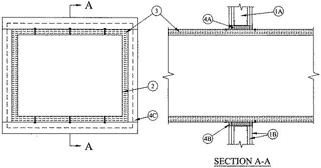
2.Steel Duct — Nom 24 by 30 in. (610 by 762 mm) (or smaller) No. 24 gauge (or heavier) steel duct to be installed eccentrically within the framed opening. Steel duct to be rigidly supported on both sides of wall assembly.
3.Batts and Blankets* — Max 1-1/2 in. (38 mm) thick glass fiber batt or blanket (min 3/4 pcf or 12 kg/m3) jacketed on the outside with a foil-scrim-kraft facing. Longitudinal and transverse joints sealed with aluminum foil tape. During the installation of the fill material, the batt or blanket shall be compressed 50% such that the annular space within the firestop system shall be min 1 in. (25 mm) to max 2-3/4 in. (70 mm).
See Batts and Blankets - (BKNV) category in the Building Materials Directory for names of manufacturers. Any batt or blanket meeting the above specifications and bearing the UL Classification Marking with a Flame Spread Index of 25 or less and a Smoke Developed Index 50 or less may be used.
4.Firestop System — The firestop system shall consist of the following:
A.Packing Material — Min 3-5/8 (92 mm) or 4-7/8 in. (124 mm) thickness of min 4 pcf (64 kg/m3) mineral wool batt insulation firmly packed into opening as a permanent form for 1 or 2 hr fire-rated walls, respectively. Packing material to be recessed from both surfaces of wall as required to accommodate the required thickness of fill material.B.Fill, Void or Cavity Material* — Sealant — Min 5/8 in. (16 mm) thickness of fill material applied within annulus, flush with both surfaces of wall.
RECTORSEAL — FS 900+ Sealant, Metacaulk MC 150+, Biostop BF 150+C.Steel Retaining Angles — Min No. 22 gauge galv steel angles sized to lap steel duct a min of 2 in. (51 mm) and lap wall surfaces a min 1-1/2 in. (38 mm). Angles attached to steel duct on both sides of wall with min No. 10 steel sheet metal screws spaced a max of 1 in. (25 mm) from each end of steel duct and spaced a max 6 in. (152 mm) OC.