W-L-7036
January 4, 2000
January 4, 2000
F Ratings — 1 and 2 Hr (See Item 1)
T Rating — 0 Hr
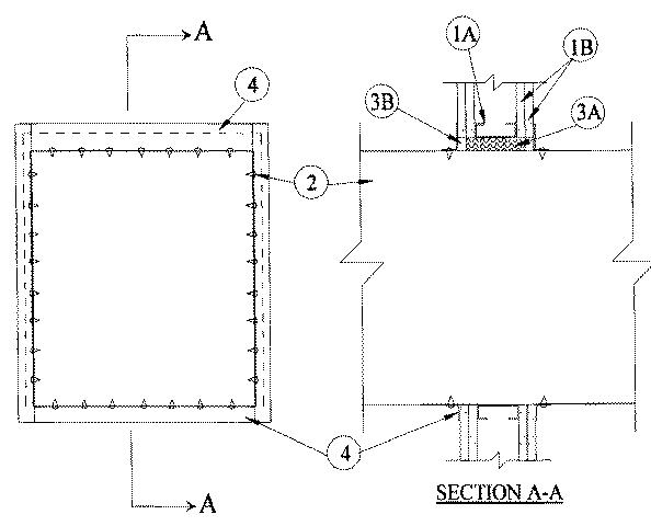
1.Wall Assembly — The 1 or 2 hr fire-rated gypsum wallboard/stud wall assembly shall be constructed of the materials and in the manner specified in the individual U400 Series Wall and Partition Designs in the UL Fire Resistance Directory and shall include the following construction features:
A.Studs — Wall framing shall consist of steel channel studs. Steel studs to be min 2-1/2 in. wide and spaced max 24 in. OC. Additional framing members shall be used to completely frame around opening.B.Gypsum Board* — Min 5/8 in. thick, 4 ft wide with square or tapered edges. The gypsum wallboard type, thickness, number of layers and orientation shall be as specified in the individual U400 Wall and Partition Design. Max size of opening is 484 sq. in. with a max dimension of 22 in.The hourly F Rating of the firestop system is equal to the hourly fire rating of the wall in which it is installed.
2.Steel Duct — Nom 21 by 21 in. (or smaller) No. 24 gauge (or heavier) steel duct to be installed either concentrically or eccentrically within the opening. The annular space shall be min 0 in. (point contact) to max 1 in. Duct to be rigidly supported on both sides of wall assembly.
3.Firestop System — The firestop system shall consist of the following:
A.Packing Material — Min 2-3/4 or 4 in. thickness of min 4 pcf mineral wool batt insulation firmly packed into opening as a permanent form for 1 or 2 hr fire rated walls, respectively . Packing material to be recessed from both surfaces of wall as required to accommodate the required thickness of fill material.B.Fill, Void or Cavity Material* — Caulk — Min 1/2 in. thickness of fill material applied within the annulus, flush with both surfaces of wall. At point contact location, a min 1/4 in. diam bead of fill material shall be applied to the wall/duct interface on both surfaces of the wall.
RECTORSEAL — Metacaulk 1000
4.Steel Retaining Angles — Nom 2 by 2 in. by No. 22 gauge (or heavier) steel angles attached to all four sides of duct on both sides of wall. The angles shall be attached to the duct with No. 8 (or larger) sheet metal screws spaced max 2 in. from each end of duct and spaced a max of 5 in. OC.