W-L-7027
February 5, 2014
February 5, 2014
| ANSI/UL1479 (ASTM E814) | CAN/ULC S115 |
|---|---|
1.Wall Assembly — The 1 or 2 hr fire-rated gypsum wallboard/stud wall assembly shall be constructed of the material and in the manner described in the individual U400, V400 or W400 Series Wall or Partition Design in the UL Fire Resistance Directory and shall include the following construction features:
A.Studs — Wall framing shall consist of min 3-5/8 in. (92 mm) wide steel channel studs spaced max 24 in. (610 mm) OC. Additional 3-5/8 in. (92 mm) wide steel studs shall be used to completely frame the opening.B.Gypsum Board* — 5/8 in. (16 mm) thick, 4 ft (1.2 m) wide with square or tapered edges. The gypsum wallboard type, thickness, number of layers, fastener type and sheet orientation shall be as specified in the individual Design in the UL Fire Resistance Directory. Max area of opening is 989 sq in. (6381 cm2) with max dimension of 43 in. (1092 mm).The hourly F and FH Ratings of the firestop system are equal to the hourly fire rating of the wall assembly in which it is installed.
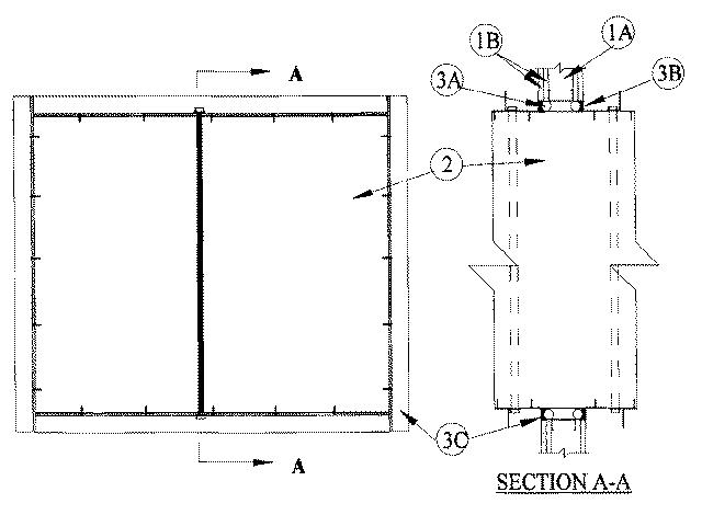
2.Steel Ducts — Nom 40 by 20 in. (1016 by 508 mm) (or smaller) No. 24 gauge (or heavier) galv steel duct to be installed either concentrically or eccentrically within the firestop system. The space between the steel duct and periphery of opening shall be min 3/4 in. (19 mm) to max 2-1/4 in. (57 mm) Steel duct to be rigidly supported on both sides of the wall assembly. During the installation of the steel duct, internal support members consisting of nom 1/2 in. (13 mm) diam threaded steel shall be installed within the center of the steel duct on both sides of wall assembly. Threaded steel rod shall extend a max 3 in. (76 mm) beyond top and bottom of steel duct and secured to top and bottom surfaces of steel duct by means of 1/2 in. (13 mm) diam steel nuts and 3/4 in. (19 mm) by 3 in. (76 mm) diam steel fender washers. Threaded steel rod to be installed a max of 6 in. (152 mm) from each side of wall. In addition to the threaded steel rod, external supports consisting of min 1-1/2 by 1-1/2 in. (38 by 38 mm) by 3/16 in. (4.8 mm) thick steel angles to be installed around the outer perimeter of the steel duct and secured to the steel duct by means of No. 10 by 3/4 in. (19 mm) long steel sheet metal screws spaced a max 8 in. (203 mm) OC. Steel angles to be installed on both sides of wall and spaced a max 12 in. (305 mm) from each surface of wall.
3.Firestop System — The firestop system shall consist of the following:
A.Packing Material — Polyethylene backer rod, mineral wool batt insulation or fiberglass batt insulation friction fitted into annular space for 2 hr fire-rated wall assemblies only. Packing material to be recessed from both surfaces of wall as required to accommodate the required thickness of fill material.B.Fill, Void or Cavity Material* — Sealant — Min 5/8 in. (16 mm) thickness of fill material applied within the annulus, flush with both surfaces of wall.
RECTORSEAL — FlameSafe FS1900, FS1901, FS1905, FS1929, Metacaulk 1000, Metacaulk 350i, Biostop 350i or Biostop 500+C.Steel Retaining Angles — Min No. 16 gauge galv steel angles sized to lap steel duct a min of 2 in. (51 mm) and lap wall surfaces a min 1 in. (25 mm) Angles attached to steel duct on both sides of wall with min No. 10 by 1/2 in. (13 mm) long steel sheet metal screws spaced a max of 1 in. (25 mm) from each end of steel duct and spaced a max 6 in. (152 mm) OC.