W-L-5250
September 22, 2005
September 22, 2005
F Rating — 2 Hr
T Rating — 2 Hr
1.Wall Assembly — The 2 hr fire-rated gypsum wallboard/stud wall assembly shall be constructed of the materials and in the manner specified in the individual U300, U400 or V400 Series Wall and Partition Designs in the UL Fire Resistance Directory and shall include the following construction features:
A.Studs — Wall framing may consist of either wood studs or steel channel studs. Wood studs to consist of nom 2 by 4 in. (51 by 102 mm) lumber spaced 16 in. (406 mm) OC. Steel studs to be min 2-1/2 in. (64 mm) wide and spaced max 24 in. (610 mm) OC. When steel studs are used and the diam of opening exceeds the width of stud cavity, the opening shall be framed on all four sides using lengths of steel stud installed between the vertical studs and screw-attached to the steel stud at each end. The framed opening in the wall shall be 2-1/2 in. (64 mm) to 6-1/2 in. (165 mm) wider and 2-1/2 in. (64 mm) to 6-1/2 in. (165 mm) higher than the diam of the insulated penetrating item such that, when the insulated penetrating item is installed in the opening, a 1-1/4 in. (32 mm) to 3-1/4 in. (83 mm) clearance is present between the insulated penetrating item and the framing in all four sides.B.Gypsum Board* — Two layers of nom 5/8 in. (16 mm) thick gypsum board, as specified in the individual Wall and Partition Design. Max diam of opening is 28 in. (711 mm) for steel stud walls. Max diam of opening is 14-1/2 in. (368 mm) for wood stud walls.
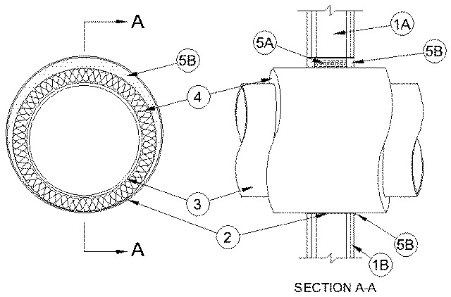
2.Steel Wire Mesh — Cylindrical sleeve fabricated from No. 8 steel wire mesh and having a min 1 in. (25 mm) lap along the longitudinal seam. Length of steel wire mesh to be 1/2 in. (13 mm) less than thickness of the wall. Steel wire mesh to be centered and formed to fit periphery of through opening.
3.Through Penetrants — One metallic pipe or tubing to be installed concentrically or eccentrically within the firestop system. Pipe or tubing to be rigidly supported on both sides of wall assembly. The following types and sizes of metallic pipes or tubing may be used:
A.Steel Pipe — Nom 20 in. (508 mm) diam (or smaller) Schedule 10 (or heavier) steel pipe.B.Iron Pipe — Nom 20 in. (508 mm) diam (or smaller) cast or ductile iron pipe.C.Copper Tubing — Nom 2 in. (51 mm) diam (or smaller) Type L (or heavier) copper tubing.D.Copper Pipe — Nom 2 in. (51 mm) diam (or smaller) Regular (or heavier) copper pipe.
4.Pipe Covering* — Nom 3 in. (76 mm) thick hollow cylindrical heavy density glass fiber units jacketed on the outside with an all service jacket. Longitudinal joints sealed with metal fasteners or factory-applied self-sealing lap tape. Transverse joints secured with metal fasteners or with butt tape supplied with the product. The annular space shall be min 0 in. (point contact) to max 2 in. (51 mm).
See Pipe and Equipment Covering — Materials (BRGU) category in the Building Materials Directory for names of manufacturers. Any pipe covering material meeting the above specifications and bearing the UL Classification Marking with a Flame Spread Index of 25 or less and a Smoke Developed Index of 50 or less may be used.
5.Firestop System — The firestop system shall consist of the following:
A.Packing Material — Min 3 in. (76 mm) thickness of min 4.0 pcf (64 kg/m3) mineral wool batt insulation firmly packed into opening as a permanent form. Packing material to be recessed from both surfaces of wall to accommodate the required thickness of fill material.B.Fill, Void or Cavity Material* — Caulk — Min 1 in. (25 mm) thickness of fill material applied within the annulus, flush with both surfaces of wall. At the point contact location between pipe insulation and wall, a min 1/4 in. (6 mm) diam bead of fill material shall be applied at the wall/pipe insulation interface on both surfaces of wall.
RECTORSEAL — Metacaulk 350i