July 16, 2014
| ANSI/UL1479 (ASTM E814) | CAN/ULC S115 |
|---|---|
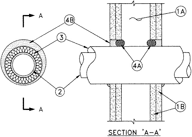
1.Wall Assembly — The 1 or 2 hr fire-rated gypsum board/stud wall assembly shall be constructed of the materials and in the manner described in the individual U300, U400 or V400 Series Wall and Partition Designs in the UL Fire Resistance Directory and shall include the following construction features:
A.Studs — Wall framing shall consist of either wood studs or steel channel studs. Wood studs to consist of nom 2 by 4 in. (51 by 102 mm) lumber spaced 16 in. (406 mm) OC. Steel studs to be min 3-5/8 in. (92 mm) wide and spaced 24 in. (610 mm) OC.B.Gypsum Board* — 5/8 in. (16 mm) thick, 4 ft (1.22 m) wide with square or tapered edges. The gypsum board type, thickness, number of layers, fastener type and sheet orientation shall be as specified in the individual U300, U400 or V400 Series Designs in the UL Fire Resistance Directory. Max diam of opening in wood stud walls is 14-1/2 in. (368 mm) Max diam of opening in steel stud walls is 18-5/16 in. (465 mm). The inside diam of the opening shall be min 1 in. (25 mm) to max 3 in. (76 mm) larger than the outside diam of pipe covering (see Item 3).
2.Through Penetrants — One metallic pipe or tube installed concentrically or eccentrically within the firestop system. Pipe or tube to be rigidly supported on both sides of the wall. The following types and sizes of through penetrants may be used:
A.Steel Pipe — Nom 12 in. (305 mm) diam (or smaller) Schedule 30 (or heavier) steel pipe.B.Iron Pipe — Nom 12 in. (305 mm) diam (or smaller) cast or ductile iron pipe.C.Copper Tubing — Nom 6 in. (152 mm) diam (or smaller) Type L (or heavier) copper tubing.D.Copper Pipe — Nom 6 in. diam (152 mm) (or smaller) Regular (or heavier) copper pipe.The type and max nom diam of the through penetrant is dependent upon the rating of the wall assembly, and the type of fill material as shown in Item 4B.
3.Pipe Covering* — One of the following types of pipe coverings shall be used:
A.Pipe and Equipment Covering Materials* — Nom 2 in. (51 mm) thick hollow cylindrical heavy density (min 3.5 pcf or 56 kg/m3) glass fiber units jacketed on the outside with an all service jacket. Longitudinal joints sealed with metal fasteners or factory-applied self-sealing lap tape. Transverse joints secured with metal fasteners or butt tape supplied with the product. The annular space between the insulated through penetrant and the periphery of the opening shall be min 0 in. (0 mm, point contact) to max 1-9/16 in. (40 mm)See Pipe and Equipment Covering Materials* (BRGU) category in the Building Materials Directory for names of manufacturers. Any pipe covering material meeting the above specifications and bearing the UL Classification Marking with a Flame Spread Index of 25 or less and a Smoke Developed Index of 50 or less may be used.
B.Pipe and Equipment Covering Materials* — Nom 2 in. (51 mm) thick unfaced mineral fiber pipe insulation having a nom density of 3.5 pcf (56 kg/m3 or heavier) and sized to the outside diam of the pipe or tube. Pipe insulation secured with min 18 AWG steel wire spaced 12 in. (305 mm) OC. The annular space between insulated penetrating item and the periphery of the through opening shall be min 0 in. (0 mm, point contact) to max 1-9/16 in. (40 mm).C.Sheathing Material* — Used in conjunction with Item 3B. Foil-scrim-kraft or all service jacket material shall be wrapped around the outer circumference of the pipe insulation (Item 3B) with the kraft side exposed. Longitudinal and transverse joints sealed with metal fasteners or butt tape.
See Sheathing Materials* (BVDV) category in the Building Materials Directory for names of manufacturers. Any sheathing material meeting the above specifications and bearing the UL Classification Marking with a Flame Spread Index of 25 or less and a Smoke Developed Index of 50 or less may be used.
4.Firestop System — The firestop system shall consist of the following:
A.Packing Material — Nom 1 in. (25 mm) foam backer rod firmly packed into the opening as a permanent form in 2 hr fire-rated assemblies to prevent leakage of fill material during installation. Packing material to be recessed from both surfaces of wall as required to accommodate the required thickness of fill material.
B.Fill, Void or Cavity Material* — Sealant Min 5/8 in. (16 mm) thickness of fill material applied within annulus, flush with each surface of wall. At point contact location, a min 3/8 in. (10 mm) bead of fill material shall be applied to the wall/pipe covering interface on both surfaces of the wall.The F and T Ratings of the firestop system are dependent upon the hourly rating of the wall assembly, max nom diam and type of the through penetrant and type of fill material as shown in the table below:
Rating of
Wall, Hr
Type of
Through
PenetrantMax Nom
Diam of
Through
Penetrant,
In. (mm)
Type of
Fill
Material
F and FH Ratings,
Hr
T, FT and FTH Rating,
Hr2 Copper Tube, Copper Pipe, Steel Pipe, or Iron Pipe 4 (102) FS1900, Metacaulk 1000, Metacaulk 350i, Biostop 350i or Biostop 500+ 2 1-1/2 1 Copper Tube, Copper Pipe, Steel Pipe, or Iron Pipe 4 (102) FS1900, Metacaulk 1000, Metacaulk 350i, Biostop 350i or Biostop 500+ 1 1 2 Copper Tube, Copper Pipe, Steel Pipe, or Iron Pipe 6 (152) FS900+, Metacaulk MC 150+, Biostop BF 150+ 2 1 1 Copper Tube, Copper Pipe, Steel Pipe, or Iron Pipe 6 (152) FS900+, Metacaulk MC 150+, Biostop BF 150+ 1 0 2 Steel Pipe, or Iron Pipe 12 (152) FS900+, FS1900, Metacaulk MC 150+, Metacaulk 1000, Metacaulk 350i, Biostop BF 150+, Biostop 350i or Biostop 500+ 2 1-1/2 1 Steel Pipe, or Iron Pipe 12 (152) FS900+, FS1900, Metacaulk MC 150+, Metacaulk 1000, Metacaulk 350i, Biostop BF 150+, Biostop 350i or Biostop 500+ 1 3/4
RECTORSEAL — FlameSafe® FS900+, FlameSafe® FS1900, Metacaulk MC 150+, Metacaulk 1000, Metacaulk 350i, Biostop BF 150+, Biostop 350i or Biostop 500+.