February 5, 2014
| ANSI/UL1479 (ASTM E814) | CAN/ULC S115 |
|---|---|
1.Wall Assembly — The 1 or 2 hr fire-rated gypsum board/stud wall assembly shall be constructed of the materials and in the manner described in the individual U400, V400 or W400 Series Wall and Partition Design in the UL Fire Resistance Directory and shall include the following construction features:
A.Studs — Wall framing may consist of min 3-5/8 in. (92 mm) wide steel channel studs spaced max 24 in. (610 mm) OC.B.Gypsum Board* — 5/8 in. (16 mm) thick, 4 ft (1.2 m) wide with square or tapered edges. The gypsum board type, thickness, number of layers, fastener type and sheet orientation shall be as specified in the individual Design in the UL Fire Resistance Directory. Max diam of opening is 21 in. (533 mm).The Ratings of the firestop system are equal to the hourly fire rating of the wall assembly in which it is installed.
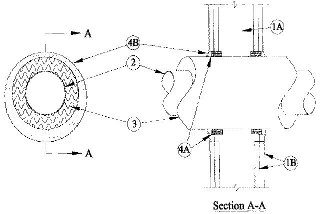
2.Through Penetrant — One metallic pipe to be installed either concentrically or eccentrically within the firestop system. Pipe to be rigidly supported on both sides of wall assembly. The following types and sizes of metallic pipes may be used:
A.Steel Pipe — Nom 12 in. (254 mm) diam (or smaller) Schedule 10 (or heavier) steel pipe.B.Iron Pipe — Nom 12 in. (254 mm) diam (or smaller) cast or ductile iron pipe.
3.Pipe Coverings* — One of the following types of pipe coverings shall be used:
A.Pipe and Equipment Covering Materials* — Nom 3 in. (76 mm) thick hollow cylindrical glass fiber units, nom 3.5 pcf (56 kg/m3) density, jacketed on the outside with an all service jacket. Longitudinal joints sealed with metal fasteners or factory-applied self-sealing lap tape. Transverse joints secured with metal fasteners or with butt tape supplied with the product. The annular space between insulated penetrant and periphery of opening shall be min 1/2 in. (13 mm) to max 1-3/4 in. (44 mm).
See Pipe and Equipment Covering-Materials (BRGU) category in the Building Materials Directory for names of manufacturers. Any pipe covering material meeting the above specifications and bearing the UL Classification Marking with a Flame Spread Index of 25 or less and a Smoke Developed Index of 50 or less may be used.
B.Pipe Covering Materials* — Nom 3 in. thick unfaced mineral fiber pipe insulation sized to the outside diam of pipe or tube. Pipe insulation secured with min 8 AWG steel wire spaced max 12 in. OC. The annular space between insulated penetrant and periphery of opening shall be min 1/2 in. to max 1-3/4 in.
INDUSTRIAL INSULATION GROUP L L C — High Temperature Pipe Insulation 1200, High Temperature Pipe Insulation BWT or High Temperature Pipe Insulation Thermaloc.C.Sheathing Material* — Used in conjunction with Item 3B. Foil-scrim-kraft or all service jacket material shall be wrapped around the outer circumference of the pipe insulation (Item 3B) with the kraft side exposed. Longitudinal joints and transverse joints sealed with metal fasteners or butt tape.
See Sheathing Materials (BVDV) category in the Building Materials Directory for names of manufacturers. Any sheathing material meeting the above specifications and bearing the UL Classification Marking with a Flame Spread Index of 25 or less and a Smoke Developed Index of 50 or less may be used.
4.Firestop System — The firestop system shall consist of the following:
A.Fill, Void or Cavity Material* — Wrap Strip — Nom 1/4 in. (6 mm) thick intumescent material faced on both sides with a plastic film, supplied in 1-1/2 in. (38 mm) wide strips. Two layers of wrap strip shall be individually wrapped around the insulated through penetrant with the ends butted and held in place with masking tape. Butted ends in successive layers shall be offset. Wrap strips are slid along the insulated through penetrant into annulus such that visible ends of the wrap strip are recessed 3/8 in. (10 mm) into the wall. One set of wrap strips to be installed on each side of wall.
RECTORSEAL — FlameSafe Wrap Strip, Metacaulk Wrap Strip or Biostop Wrap StripB.Fill, Void or Cavity Material* — Sealant — Min 5/8 in. (16 mm) thickness of fill material applied within the annulus, flush with both surfaces wall. Additional fill material to be installed such that a min 3/8 in. (10 mm) crown is formed around the insulated penetrant.
RECTORSEAL — FlameSafe FS1900, FS1901, FS1905, FS1929, Metacaulk 1000, Metacaulk 350i, Biostop 350i or Biostop 500+