W-L-4054
July 19, 2005
July 19, 2005
F Rating — 1 or 2 Hr
T Rating — 0 Hr
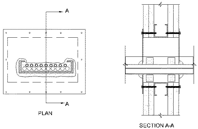
1.Wall Assembly — The 1 or 2 hr fire rated gypsum board/stud wall assembly shall be constructed of the materials and in the manner specified in the individual U300, U400 or V400 Series Wall and Partition Designs in the UL Fire Resistance Directory and shall include the following construction features:
A.Studs — Wall framing may consist of either wood studs or steel channel studs. Wood studs to consist of nom 2 by 4 in. lumber spaced 16 in. O.C. Steel channel studs to be min 3-1/2 in. wide and spaced max 24 in. O.C. Additional studs shall be used to completely frame the opening.B.Gypsum Board* — 5/8 in. thick, 4 feet wide with square or tapered edges. Thickness, type, number of layers and fastener type as specified in the individual Wall and Partition Design. Max size of opening is 12 in. by 24 in.
2.Cable Tray — Max 18 in. wide by max 4 in. deep open-ladder cable tray with channel-shaped side rails formed of min 0.13 in. thick fiberglass with nom 2 in. diam rungs spaced 9 in. O.C. or max 18 in. wide by max 4 in. deep open ladder steel or aluminum cable tray. The min annular space between the cable tray and the periphery of opening shall be 0 in. (point contact). The max annular space between the cable tray and the side periphery of the opening shall be 5 in. Cable tray to be rigidly supported on both sides of wall assembly.
3.Cables — Max 40 percent fill (based on a 3 in. loading depth within the cable tray) of any combination of cables. The following types of cables may be used:
A.Max 750 MCM power cables; THHN or THWN jacketed. B.Max 8C, No.12 AWG multiconductor power and control cables; PVC jacketed. C.Multiple fiber optical communication cable jacketed with PVC. D.Max 25 pr/24 AWG telephone cable with polyethylene insulation and PVC jacket. E.Max 300 pr/24 AWG telephone cable with polyethylene insulation and PVC jacket
4.Firestop System — The firestop system shall consist of the following items:
A.Fill, Void or Cavity Material* — Intumescent Block — The block material cross-section is nom 1 in. square. The fill material is cut into 10 in. long blocks installed within the opening on each side of the wall centered on top of cables and 8 in. long blocks installed within the opening centered on each side on bottom of framed opening.
RECTORSEAL — Metacaulk Bixi StixB.Fill, Void or Cavity Materials* — Putty Strip — (Optional) 1 in. by 1 in. by 1/8 in. thick putty pad strip installed between adjacent cables.
RECTORSEAL — Metacaulk Fire Rated Putty, Fire Rated Putty PadC.Steel Cover Plate — Cover plate is formed of min 0.028 in., 24 gauge galv. steel overlapping onto wall a min 1-1/2 in., cut to fit contour of the cable bundle with a nom 1/4 in. gap. Cover plate is attached to each side of wall with min 1-7/8 in. laminate screws and washers spaced max 4 in. O.C. Where cover sheet splices exist, attach separate 24 gauge galv. steel overlapping splice by a min 1-1/2 in. and attached with sheet metal screws spaced max 3 in. O.C. on both sides of the splice joint. As an option to separate steel splice, cover plate halves may overlap by a min 1-1/2 in. and attach together with sheet metal screws spaced max 3 in. O.C.D.Fill, Void or Cavity Materials* — Putty — Putty shall be packed around the perimeter of the cable bundle at its egress from the steel cover plate. The "dome" of putty shall be min 1 in. thick and extend a min of 1/2 in. onto the steel cover plate.
RECTORSEAL — Metacaulk Fire Rated Putty