W-L-3440
January 31, 2018
January 31, 2018
| ANSI/UL1479 (ASTM E814) | CAN/ULC S115 |
|---|---|
1.Wall Assembly — The 1 or 2 hr fire-rated gypsum board/stud wall assembly shall be constructed of the materials and in the manner specified in the individual U300, U400, V400 or W400 Series Wall and Partition Designs in the UL Fire Resistance Directory and shall include the following construction features:
A.Studs — Wall framing may consist of either wood studs or steel channel studs. Wood studs to consist of nom 2 by 4 in. (51 by 102 mm) lumber spaced 16 in. (406 mm) OC. Steel studs to be min 3-5/8 in. (91 mm) wide and spaced max 24 in. (610 mm) OC.B.Gypsum Board* — One or two layers of nom 5/8 in. (16 mm) thick gypsum board as specified in the individual Wall and Partition Design. Opening may be circular or elliptical in shape. Max diam of opening is 6-1/2 in. (165 mm) with max area of 17.87 in2.The hourly F, T, FH and FTH Ratings of the firestop system are equal to the hourly fire rating of the wall assembly.
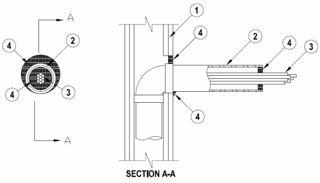
2.Sleeve — Nom 3 in. (76 mm) diam (or smaller) steel EMT, steel conduit or Schedule 5 (or heavier) steel pipe. The steel sleeve may be installed at an angle not greater than 45 degrees from perpendicular. The annular space between sleeve and periphery of opening shall be min. 0 in. (point contact) to max 1 in. (25 mm). Maximum projection from wall is 12 in. (305 mm). Sleeve to be rigidly supported on penetrated side of wall assembly.
3.Cables — Aggregate cross-sectional area of cables to be min 25 percent to max 64 percent of the aggregate cross-sectional area of the opening. Cables to be tightly bundled and rigidly supported on the penetrated side of wall assembly. The annular space between the cables and the sleeve shall be min 0 in. (point contact) to max 2 in. (51 mm). Any combination of following types and sizes of copper conductor cables may be used:
A.Max 2/C with ground, No. 12 AWG MC (BX) cable with polyvinyl chloride (PVC) insulation on conductors inside a steel armored jacket. B.Max 3/C with ground, No. 12 AWG (or smaller) nonmetallic sheathed (Romex) cable with copper conductors, PVC insulation and jacket. C.Max 8/C No. 12 AWG (or smaller) Type SOW-A P-123-70-MSHA. D.Max 25 pair, No. 24 AWG (or smaller) copper conductor telephone cable with XLPE/PVC insulation, with or without PVC jacket. E.Max RG6 (or smaller) television coaxial cable CATVX. F.Max 4 pair, No. 24 AWG (or smaller) copper conductor data cable with Hylar insulation and jacketing. G.Max 1/C, No. 18 AWG (or smaller) Type MTW or THHN or THWN or gas & oil res II 600V (UL) or AWM VW-1 power cable. H.Max 1/C, No. 14 AWG (or smaller) Type MTW or THHN or THWN or gas & oil res II 600V (UL) or AWM VW-1 power cable. I.Max 1/C, No. 10 AWG (or smaller) Type THHN or THWN gasoline & oil resistant II 600V VW-1 E116364 (UL) power cable. J.Optical Fiber Cable max 62.5/125 Type UFNR. K.Max 3/C, No. 4/0 with ground, AWG aluminum Triple E Alloy AA8176 Type SE cable Style U Type XHH-W-2 CDRS E32071 (UL) service entrance cable. L.Max 3/C, No. 18 AWG with ground and shield E120910.
4.Fill, Void or Cavity Material*— Sealant — Min 5/8 in. (16 mm) thickness of fill material applied within the annulus, flush with surface of wall. Min. 1/2 in. thickness of fill material installed within the sleeve, flush with the end of the sleeve. Min 1/4 in. (6 mm) diam bead of sealant applied at point contact location.
RECTORSEAL — Metacaulk 150+, Metacaulk 1000, Metacaulk Fire Rated Putty, Biostop 150+, Biostop 500+, Biostop Fire Rated Putty
5.Packing Material — (Optional, Not Shown) — Mineral wool forming material or foam backer rod may be used as a backer for the sealant. When used, it shall be firmly packed into annular space between cables and sleeve as a permanent form and recessed from end of sleeve to accommodate the required thickness of fill material.