W-L-3233
October 5, 2015
October 5, 2015
| ANSI/UL1479 (ASTM E814) | CAN/ULC S115 |
|---|---|
1.Wall Assembly — The 1 or 2 hr fire-rated gypsum board/stud wall assembly shall be constructed of the materials and in the manner described in the individual U300, U400, V400 or W400 Series Wall and Partition Designs in the UL Fire Resistance Directory and shall include the following construction features:
A.Studs — Wall framing shall consist of either wood studs or steel channel studs. Wood studs to consist of nom 2 by 4 in. (51 by 102 mm) lumber spaced 16 in. (406 mm) OC. Steel studs to be min 3-5/8 in. (92 mm) wide and spaced 24 in. (610 mm) OC.B.Gypsum Board* — 5/8 in. (16 mm) thick, 4 ft (1219 mm) wide with square or tapered edges. The gypsum board type, thickness, number of layers, fastener type and sheet orientation shall be as specified in the individual U300, U400, V400 or W400 Series Designs in the UL Fire Resistance Directory.The hourly F and FH Ratings of the firestop system are equal to the hourly fire rating of the wall assembly in which it is installed.
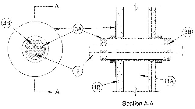
2.Cables — Aggregate cross-sectional area of cables in Threaded Sleeve to be min 8 percent to max 48 percent of the aggregate cross-sectional area of the Threaded Sleeve. Cables to be rigidly supported on both sides of wall assembly. Any combination of the following types and sizes of cables may be used:
A.Max 200 pair No. 24 AWG (or smaller) copper conductor cable with polyvinyl chloride (PVC) jacketing and insulation. B.Max 1/C, 750 kcmil power cable with copper conductors and cross-linked polyethylene (XLPE) jacketing. C.Max 3/C No. 2/0 AWG (or smaller) aluminum or copper conductor service entrance cable with PVC insulation and jacket. D.Max 3/C No. 8 AWG (or smaller) nonmetallic sheathed (Romex) cable with copper conductors, PVC insulation and jacket. E.Max 7/C No. 2/0 AWG (or smaller) multiconductor power and control cables with XLPE or PVC insulation and XLPE or PVC jacket. F.Max RG59/U (or smaller) coaxial cable with fluorinated ethylene insulation and jacketing. G.Max 62.5/48 fiber optic cable with PVC insulation and jacketing. H.Max 4 pair No. 24 AWG (or smaller) copper conductor category 5 with Hylar insulation and jacket.
3.Firestop System — The firestop system shall consist of the following:
A.Firestop Device* — Threaded steel sleeve device incorporating flat washers secured by threaded couplers. Device shall be installed in accordance with the accompanying installation instructions. Device provided in nom 1, 2 and 4 in. (25, 51 and 102 mm) sizes. Max diam of opening in wall for 1, 2 and 4 in. (25, 51 and 102 mm) size devices are 1-1/4, 2-7/16 and 4-1/2 in. (32, 62 and 114 mm) respectively.
UNIQUE FIRE STOP PRODUCTS INC — Threaded FirestopB.Fill, Void or Cavity Material* - Putty — Min 1 in. (25 mm) thickness of fill material applied within the Threaded Sleeve, flush with both ends.
HILTI CONSTRUCTION CHEMICALS, DIV OF HILTI INC — CP 618 Firestop Putty Stick
RECTORSEAL — Metacaulk Fire Rated Putty
SPECIFIED TECHNOLOGIES INC — SpecSeal Putty