W-L-3122
September 2, 2015
September 2, 2015
| ANSI/UL1479 (ASTM E814) | CAN/ULC S115 |
|---|---|
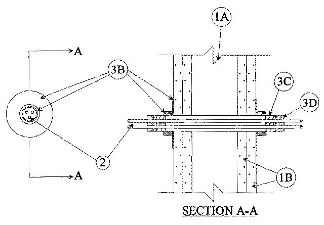
1.Wall Assembly — The 1 or 2 hr fire rated gypsum wallboard/stud wall assembly shall be constructed of the materials and in the manner specified in the individual U300, U400, V400 or W400 Series Wall and Partition Designs in the UL Fire Resistance Directory and shall include the following construction features:
A.Studs — Wall framing may consist of either wood studs or steel channel studs. Wood studs to consist of nom 2 by 4 in. (52 by 102 mm) lumber spaced 16 in. (406 mm) OC. Steel studs to be min 2-1/2 in. (64 mm) wide and spaced max 24 in. (610 mm) OC.B.Gypsum Board* — 5/8 in. (16 mm) thick, 4 ft (1219 mm) wide with square or tapered edges. The gypsum wallboard type, thickness, number of layers, fastener type and sheet orientation shall be as specified in the individual U300, U400, V400 or W400 Series Design in the UL Fire Resistance Directory. Max diam of opening is 4-1/2 in. (114 mm).The hourly Fand FH ratings of the firestop system are equal to the hourly fire rating of the wall assembly in which it is installed.
2.Cables — Aggregate cross-sectional area of cables in steel sleeve to be 45 percent of the aggregate cross-sectional area of the sleeve. Cables to be rigidly supported on both sides of wall assembly. Any combination of the following types and sizes of copper conductor cable may be used:
A.Max 300 kcmil single conductor Type MTW, THHN, THWN or AWM power cables; cross-linked polyethylene (XLPE) insulation. B.Max 4 pair No. 24 AWG telephone cable intended for plenum applications. C.Max 3/C No. 12 AWG with polyvinyl chloride (PVC) insulation and jacket.
3.Firestop System — The firestop system shall consist of the following:
A.Fill, Void or Cavity Material* — Sealant — (not shown) — Min 1/2 in. (13 mm) diam of sealant shall be applied around the perimeter of the firestop device on each side of the wall.
RECTORSEAL — Metacaulk 1000B.Firestop Device* — One of the following firestop devices may be used:
1.Smooth steel sleeve device incorporating flat washers secured by sliding compression couplers. Device shall be installed in accordance with the accompanying installation instructions. Device provided in nom 1, 2 and 4 in. (25, 51, 102 mm) sizes. Max diam of opening in wall for 1, 2 and 4 in. (25, 51, 102 mm) sizes are 1-1/8, 2-1/4 and 4-1/2 in. (29, 57, 114 mm), respectively.
UNIQUE FIRE STOP PRODUCTS INC — Smooth Firestop2.Threaded steel sleeve device incorporating flat washers secured by threaded couplings. Device shall be installed in accordance with the accompanying installation instructions. Device provided in nom 1, 2 and 4 in. (25, 51, 102 mm) sizes. Max diam of opening in wall for 1, 2 and 4 in. (25, 51, 102 mm) size devices are 1-5/16, 2-3/8 and 4-1/2 in., (33, 60, 114 mm) respectively.
UNIQUE FIRE STOP PRODUCTS INC — Threaded Firestop3.Threaded steel sleeve halves incorporating split nuts and split washers sized to fit the specific diam of the opening. Device shall be installed around cables in accordance with the accompanying installation instructions. Device provided in nom 1, 2 and 4 in. (25, 51, 102 mm) sizes. Max diam of opening in wall for 1, 2 and 4 in. (25, 51, 102 mm) size devices are 1-1/4, 2-7/16 and 4-1/2 (32, 62, 114 mm) respectively.
UNIQUE FIRE STOP PRODUCTS INC — Split SleeveThe L Rating of the firestop system is dependent upon the type of firestop device as tabulated below:
Firestop
DeviceL Rating, CFM/sq ft (CFM/firestop device) Ambient 400F Smooth Firestop 22 (2) 18 (2) Threaded Firestop 22 (2) 18 (2) Split Sleeve 54 (5) 47 (4) C.Packing Material - (Optional) — Min 1 in. (25 mm) thickness of min 4.0 pcf (64 kg/m3) mineral wool batt insulation firmly packed into each end of firestop device as a permanent form. Packing material to be recessed from each end of firestop device as required to accommodate the required thickness of fill material.D.Fill, Void or Cavity Material* — Putty — Min 5/8 in. (16 mm) thickness of fill material applied within the firestop device, flush with both ends.
RECTORSEAL — Metacaulk Fire Rated Putty