W-L-3005
October 25, 2019
October 25, 2019
F Ratings — 1 and 2 Hr (See Item 1)
T Ratings — 1/2 Hr

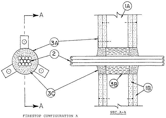
1.Wall Assembly — The 1 or 2 hr fire-rated gypsum board/stud wall assembly shall be constructed of the materials and in the manner specified in the individual U300, U400, V400 or W400 Series Wall and Partition Designs in the UL Fire Resistance Directory and shall include the following construction features:
A.Studs — Wall framing may consist of either wood studs or steel channel studs. Wood studs to consist of nom 2 by 4 in. (51 by 102 mm) lumber spaced 16 in. (406 mm) OC. In 2 hr fire-rated assemblies, steel studs to be min 2-1/2 in. (64 mm) wide and spaced max 24 in. (610 mm) OC. In 1 hr fire-rated assemblies, steel studs to be min 3-5/8 in. (92 mm) wide and spaced max 24 in. (610 mm) OC.B.Gypsum Board* — 5/8 in. (16 mm) thick, 4 ft (1.2 m) wide with square or tapered edges. The gypsum board type, thickness, number of layers, fastener type and sheet orientation shall be as specified in the individual Design in the UL Fire Resistance Directory. Max diam of opening is 3 in. (76 mm).The hourly F rating of the firestop system is equal to the hourly fire rating of the wall assembly in which it is installed.
2.Cables — Aggregate cross-sectional area of cable in opening to be max 40 percent of the aggregate cross-sectional of the opening. Cables to be centered and rigidly supported on both sides of floor or wall assembly. The following types and sizes of copper conductor cables may be used:
A.Max 50 pair No. 24 AWG (or smaller) copper conductor telephone cables with polyvinyl chloride (PVC) insulation and jacket materials. B.Max 2/C (with ground) No. 12 AWG (or smaller) PVC insulated and jacketed nonmetallic sheathed cable.
3.Firestop System — The firestop system shall consist of the following:
A.Steel Sleeve — Cylindrical sleeve friction fitted into the opening with nom 1 by 1 in. (25 by 25 mm) long mounting flanges and secured to gypsum wallboard with 2 in. (51 mm) long Type S self-drilling, self-tapping steel screws and fender washers. Sleeve may be field fabricated from min 0.016 in. (0.4 mm) thick (No. 30 gauge) galv sheet metal in accordance with the manufacturer's installation instructions.B.Packing Material — In 2 hr fire-rated assemblies, min 2-1/2 in. (64 mm) thickness of min 4 pcf (64 kg/m3) mineral wool insulation firmly packed into opening as a permanent form. In 1 hr fire-rated assemblies, min 2-3/8 in. (60 mm) thickness of min 4 pcf (64 kg/m3) mineral wool insulation firmly packed into opening as a permanent form. Packing material to be recessed from both surfaces of wall as required to accommodate the required thickness of fill material.C.Fill, Void or Cavity Material* — Caulk or Putty — Min 1-1/4 in. (32 mm) thickness of fill material applied within annulus flush with both surfaces of wall. Fill material to be forced into interstices of cable bundle max extent possible. Additional fill material to be installed such that a min 1/2 in. (13 mm) crown is formed around the penetrating item.
RECTORSEAL —FS900, FS901, FS903, FS903CG, FS905, FS905CG, FS929, FST901, FST903, FST905, Metacaulk 150+ or FSP 1000 Putty