December 22, 2023
December 22, 2023
|
ANSI/UL1479 (ASTM E814) |
CAN/ULC S115 |
|
F Rating — 1 and 2 Hr (See Item 1) |
F Rating — 1 and 2 Hr (See Item 1) |
|
T Ratings — 0, 1 and 2 Hr (see Item 1 and 3) |
FT Ratings — 0, 1 and 2 Hr (see Item 1 and 3) |
|
|
FH Rating — 1 and 2 Hr (See Item 1) |
|
|
FTH Ratings — 0, 1 and 2 Hr (see Item 1 and 3) |
System tested with a pressure differential of 2.5 Pa between the exposed and the unexposed surfaces with the higher pressure on the exposed side.
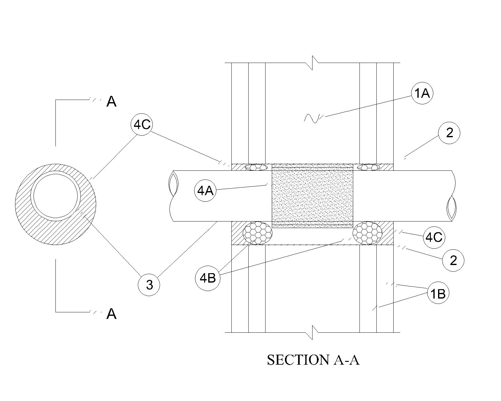
1. Wall Assembly — The 1 or 2 hr fire-rated gypsum board/stud wall assembly shall be constructed of the materials and in the manner specified in the individual U300, U400, V400 or W400 Series Wall and Partition Designs in the UL Fire Resistance Directory and shall include the following construction features:
A. Studs — Wall framing may consist of either wood studs or steel channel studs. Wood studs to consist of nom 2 by 4 in. (51 X 102 mm) lumber spaced 16 in. (406 mm) OC. Steel studs to be min 3-1/2 in. (89 mm) wide and spaced max 24 in.(610 mm) OC.
B. Gypsum Board* — Min 5/8 in. (16 mm) thick. The gypsum board type, thickness, number of layers, fastener type and sheet orientation shall be as specified in the individual design in the UL Fire Resistance Directory. Max diameter of opening is 6 in. (152 mm). see Table 1.
The hourly Ratings of the firestop system are equal to the hourly fire rating of the wall assembly in which it is installed.
2. Metallic Sleeve — Nom 6 in. (102 mm) (or smaller) cylindrical sleeve fabricated from min 0.018 in. (0.46 mm) thick (28 gauge) galv sheet steel and having a min 1 in. (25 mm) lap along longitudinal seam. Length of sleeve to be installed flush with wall surfaces.
3. Through Penetrants — One nonmetallic pipe, conduit or tubing to be centered within the firestop system. The max diam of the through penetrant and annular space within the firestop system is dependent upon the quantity of fill material (Item 4). Pipe, conduit or tubing to be rigidly supported on both sides of the wall assembly. The following types and sizes of nonmetallic pipes, conduits or tubing may be used:
A. Polyvinyl Chloride (PVC) Pipe — Nom 4 in. (102 m) diam (or smaller) Schedule 40 solid core PVC pipe for use in closed (process or supply) piping systems.
B. Chlorinated Polyvinyl Chloride (CPVC) Pipe — Nom 4 in. (102 m) diam (or smaller) SDR 13.5 CPVC pipe for use in closed (process or supply) piping systems.
C. Polyvinyl Chloride-XFR (PVC-XFR) Pipe — Nom 4 in. (102 mm) diam (or smaller) Schedule 40 solid core PVC-XFR pipe for use in closed (process or supply) or vented (drain, waste or vent) piping systems
D. Rigid Nonmetallic Conduit+ — Nom 4 in. (102 mm) diam (or smaller) Schedule 40 PVC conduit installed in accordance with the National Electrical Code (NFPA No. 70).
E. Electrical Nonmetallic Tubing (ENT)+ — Nom 4 in. (102 mm) diam (or smaller) PVC tubing installed in accordance with the National Electrical Code (NFPA No. 70).
F. Acrylonitrile Butadiene Styrene (ABS) Pipe —Nom 4 in. (102 mm) diam (or smaller) Schedule 40 solid or cellular core ABS pipe for use in closed (process or supply) or vented (drain, waste or vent) piping systems Note when ABS penetrant is used T, FT and FTH ratings are 0Hr
G. Polypropylene (PP-R) Pipe — Nom 4 in. (102mm) diam (or smaller) Aquatherm or Niron SDR 11 PP pipe for use in closed (process or supply) piping systems.
G1 Polypropylene PP-RCT Pipe — As an alternate to Item G, nom 4 in. (102 mm) diam (or smaller) Aquatherm or Niron SDR 11 PP-RCT pipe for use in closed (process or supply) piping systems.
H. High Density Polyethylene (HDPE) Pipe — Nom 4 in. (102 mm) diam (or smaller) SDR11 HDPE pipe for use in closed (process or supply) piping systems.
Penetrants G, G1, H are limited to only ANSI/UL 1479 (ASTM E 814)
4. Firestop System — The firestop system shall consist of the following:
A. Fill, Void or Cavity Materials* — Two layers of Nom 2 mm thick by 3 in. (76 mm) wide intumescent joint strip. Strips tightly wrapped around the outer circumference of the pipe with ends butted and held in place with tape. Joint strip slid into the annular space and centered in depth of wall. The edge of the joint strip recessed min 5/8 (16 mm) or 1-1/4 in. (32 mm), from both surfaces of wall. for 1 and 2 hour rated wall respectively
B. Fill, Void or Cavity Material* — Sealant — min 1/4 in. (6 mm) thickness of fill material applied within the annulus, flush with both surfaces of wall.
C. Fill, Void or Cavity Material* — Sealant — min 1/4 in. (6 mm) thickness of fill material applied within the annulus, flush with both surfaces of wall.
The max diam of the through penetrant and annular space within the firestop system is dependent upon the quantity of fill material as tabulated below:
Table 1:
|
|
In. (mm) |
layers |
Min Annular Space in. (mm) |
in. (mm) |
In. (mm) |
In. (mm) |
|
A, B, C, D, E, F, H |
3(76) |
1 |
1/16 (3.2) |
1/4 (6) |
4 (102) |
1/4 (6) |
|
A, B, C, D, E, F, H |
4 (102) |
2 |
3/16 (4.8) |
1/4 (6) |
5 (127) |
1/4 (6) |
|
G, G1 |
3(76) |
1 |
1/16 (3.2) |
1 (25) |
5 (127) |
1/4 (6) |
|
G, G1 |
4 (102) |
2 |
3/16 (3.2) |
1 (25) |
6 (152) |
1/4 (6) |