W-L-2569
October 1, 2012
October 1, 2012
| ANSI/UL1479 (ASTM E814) | CAN/ULC S115 |
|---|---|
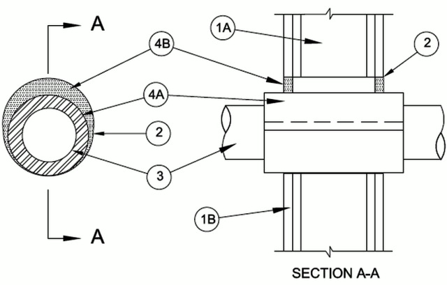
1.Wall Assembly — The 1 or 2 hr fire-rated gypsum board/stud wall assembly shall be constructed of the materials and in the manner described in the individual U300, U400, V400 or W400 Series Wall and Partition Design in the UL Fire Resistance Directory and shall include the following construction features:
A.Studs — Wall framing may consist of either wood studs or steel channel studs. Wood studs to consist of nom 2 by 4 in. (51 by 102 mm) lumber spaced 16 in. (406 mm) OC. Steel studs to be min 3-5/8 in. (92 mm) wide and spaced max 24 in. (610 mm) OC.B.Gypsum Board* — 5/8 in. (16 mm) thick, 4 ft (1.2 m) wide with square or tapered edges, The gypsum board type, thickness, number of layers, fastener type and sheet orientation shall be as specified in the individual U300, U400, V400 or W400 Series Design in the UL Fire Resistance Directory. Max diam of opening is 10-1/2 in. (267 mm).The hourly F Rating of the firestop system is dependent on the hourly fire rating of the wall assembly in which it is installed.
2.Metallic Sleeve — (Optional) Cylindrical sleeve fabricated from min 0.018 in. (0.46 mm) thick (28 gauge) galv sheet steel and having a min 1 in. (25 mm) lap along the longitudinal seam. Sheet steel coiled to a diam less than circular cutouts in wall assembly, inserted through both sides of wall and allowed to uncoil against the circular cutouts in the wall assembly. Sleeve to be installed flush with or extending max 1 in. (25 mm) beyond each surface of the wall assembly.The T Rating of the firestop system is 0 hr when sleeve extends beyond either surface of the wall.
3.Through Penetrants — One nonmetallic pipe or conduit to be installed either concentrically or eccentrically within the firestop system. The annular space between the pipe or conduit and periphery of opening shall be min 1/4 in. (6 mm) to max 1 in. (25 mm). Pipe or conduit to be rigidly supported on both sides of the wall assembly. The following types and sizes of nonmetallic pipes may be used:
A.Polyvinyl Chloride (PVC) Pipe — Nom 8 in. (203 mm) diam (or smaller) Schedule 40 solid or cellular core PVC pipe for use in closed (process or supply) or vented (drain, waste or vent) piping systems.B.Chlorinated Polyvinyl Chloride (CPVC) Pipe — Nom 8 in. (203 mm) diam (or smaller) SDR 13.5 CPVC pipe for use in closed (process or supply) piping systems.C.Rigid Nonmetallic Conduit+ — Nom 6 in. (152 mm) diam (or smaller), Schedule 40, PVC conduit installed in accordance with the National Electrical Code (NFPA No. 70).D.Acrylonitrile Butadiene Styrene (ABS) Pipe — Nom 4 in. (102 mm) diam (or smaller) Schedule 40 solid or cellular core ABS pipe for use in closed (process or supply) or vented (drain, waste or vent) piping systems.E.Polyvinylidene Fluoride (PVDF) Pipe — Nom 4 in. (102 mm) diam (or smaller) Schedule 40 PVDF pipe for use in closed (process or supply) or vented (drain, waste or vent) piping systems.The T Rating is 2 hr for Penetrants A, B and C. The T Rating for Penetrant D is 0 hr. The T Rating for Penetrant E is 1/4 hr.
4.Firestop System — The firestop system shall consist of the following:
A.Firestop Device — Galv steel sleeve lined with an intumescent material sized to fit the specific diam of the through penetrant. Device to be installed in accordance with the manufacturer's installation instructions along with the following: Device to be wrapped around outer circumference of through penetrant and installed through the annular space of the opening. The device shall be secured together by means of min 3/4 in. (19 mm) wide glass cloth electrical tape, duct tape, fiberglass tape, pop rivets, hose clamps or tie wires around the outer circumference of through penetrant, spaced max 2 in. (51 mm) OC. In walls having a nominal thickness of 8 in. (203 mm) or less, the device shall be centered within the wall and extend equally beyond each surface of the wall. In walls having a nominal thickness greater than 8 in. (203 mm) , two devices shall be installed within the opening with butted ends and extending equally beyond each surface of the wall.
RECTORSEAL — FlameSafe® Intumescent Sleeve, Metacaulk Intumescent Sleeve or Biostop Intumescent SleeveB.Fill, Void or Cavity Material* — Sealant — Min 5/8 in. (16 mm) thickness of fill material applied within the annulus, flush with both surfaces of wall.
RECTORSEAL — Metacaulk 1000, 150+, Biostop 500+, 150+, FlameSafe 1900, 900+C.Fill, Void or Cavity Material* — (Optional) — Min 1/2 in. (13 mm) thickness of fill material applied within the annulus, flush with top of the friestop device.
RECTORSEAL — Metacaulk 1000, 150+, Fire rated putty, Biostop 500+, 150+, Fire rated putty, FlameSafe 1900, 900+ , Fire rated putty.The L Rating is less than one CFM when Item RC is used.