W-L-2465
February 5, 2014
February 5, 2014
F Ratings — 1 and 2 Hr (See Item 1)
T Ratings — 1 and 2 Hr (See Item 1)
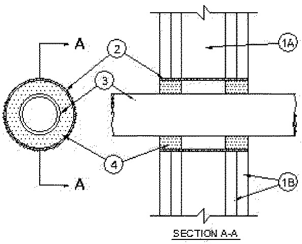
1.Wall Assembly — The 1 or 2 hr fire-rated gypsum board/stud wall assembly shall be constructed of the materials and in the manner specified in the individual U300, U400, V400 or W400 Series Wall and Partition Designs in the UL Fire Resistance Directory and shall include the following construction features:
A.Studs — Wall framing may consist of either wood studs or steel channel studs. Wood studs to consist of nom 2 by 4 in. (51 X 102 mm) lumber spaced 16 in. (406 mm) OC. Steel studs to be min 2-1/2 in. (64 mm) wide and spaced max 24 in.(610 mm) OC.B.Gypsum Board* — Min 5/8 in. (16 mm) thick. The gypsum board type, thickness, number of layers, fastener type and sheet orientation shall be as specified in the individual design in the UL Fire Resistance Directory. Max diameter of opening is 4-3/8 in. (111 mm)The hourly Ratings of the firestop system are equal to the hourly fire rating of the wall assembly in which it is installed.
2.Metallic Sleeve — Nom 4 in. (102 mm) (or smaller) cylindrical sleeve fabricated from min 0.018 in. (0.46 mm) thick (28 gauge) galv sheet steel and having a min 1 in. (25 mm) lap along longitudinal seam. Length of sleeve to be installed flush with wall surfaces or extending a max 1 in. (25 mm) from wall surfaces.
2A.Metallic Sleeve — As an alternate to Item 2, steel sleeve may consist of max 4 in. (102 mm) diameter Schedule 5 (or heavier) steel pipe, rigid steel conduit or EMT friction-fitted into wall assembly flush with or extending a max 4 in. (102 mm) beyond each surface of the wall assembly.
3.Through Penetrants — One nonmetallic pipe, conduit or tubing to be centered within the firestop system. The max diam of the through penetrant and annular space within the firestop system is dependent upon the type of fill material (Item 4). Pipe, conduit or tubing to be rigidly supported on both sides of the wall assembly. The following types and sizes of nonmetallic pipes, conduits or tubing may be used:
A.Polyvinyl Chloride (PVC) Pipe — Nom 2 in. (51 m) diam (or smaller) Schedule 40 solid core PVC pipe for use in closed (process or supply) piping systems.B.Chlorinated Polyvinyl Chloride (CPVC) Pipe — Nom 2 in. (51 mm) diam (or smaller) SDR 13.5 CPVC pipe for use in closed (process or supply) piping systems.C.Rigid Nonmetallic Conduit+ — Nom 2 in. (51 mm) diam (or smaller) Schedule 40 PVC conduit installed in accordance with the National Electrical Code (NFPA No. 70).D.Electrical Nonmetallic Tubing (ENT)+ — Nom 1 in. (25 mm) diam (or smaller) PVC tubing installed in accordance with the National Electrical Code (NFPA No. 70).
4.Fill, Void or Cavity Mat1erial* — Sealant — In 2 hr fire rated assemblies, min 1-1/4 in. (32 mm) thickness of fill material applied within the annulus, flush with both surfaces of wall. In 1 hr fire rated assemblies, min 5/8 in. (16 mm) thickness of fill material applied within the annulus, on both surfaces of wall. Additional fill material to be installed such that a min 5/8 in. (16 mm) thick crown is formed around the penetrating item and lapping a min 1 in. (25 mm) beyond the periphery of the opening.The max diam of the through penetrant and annular space within the firestop system is dependent upon the type of fill material as tabulated below:
Max Diam of Through
Penetrant In. (mm)Nom Annular
Space In. (mm)
Fill Mtl Type1 (25) 1/2 (13) FSP 1100 Putty 2 (51) 1 (25) FS 1900 Sealant
RECTORSEAL — FlameSafe FSP 1100, FS 1900, Metacaulk 1000, Metacaulk 350i, Biostop 350i or Biostop 500+