W-L-2316
June 2, 2011
June 2, 2011
F Ratings — 1 and 2 Hr (See Item 1)
T Rating — 0 Hr

1.Wall Assembly — The 1 or 2 hr fire-rated gypsum board/stud wall assembly shall be constructed of the materials and in the manner specified in the individual U300, U400 or V400 Series Wall and Partition Designs in the UL Fire Resistance Directory and shall include the following construction features:
A.Studs — Wall framing shall consist of either wood or steel channel studs. Wood studs to consist of nom 2 by 4 in. (51 by 102 mm) lumber spaced 16 in. (406 mm) OC. Steel studs to be min 2-1/2 in. (64 mm) wide and spaced max 24 in. (610 mm) OC.B.Gypsum Board* — Min 5/8 in. (16 mm) thick, 4 ft (1.22 m) wide with square or tapered edges. The gypsum board type, thickness, number of layers and orientation shall be as specified in the individual Wall and Partition Design. Max diam of opening is 5-1/2 in. (140 mm).The hourly F Rating of the firestop system is equal to the fire rating of the wall assembly in which it is installed.
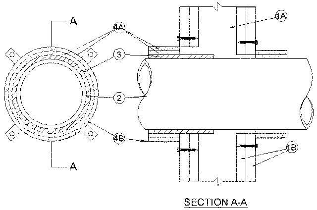
2.Through Penetrant — One nonmetallic pipe to be installed eccentrically or concentrically within the firestop system. An annular space of min 0 in. (point contact) to max 1/2 in. (13 mm) between the pipe coupler (Item 3) and the periphery of the opening is required within the firestop system on the side of the wall containing the pipe coupler. The pipe shall be installed eccentrically within the opening on the opposite side of the wall with an annular space of 0 in. (point contact) to max 1/2 in. (13 mm). Pipe to be rigidly supported on both sides of wall assembly. The following types and sizes of nonmetallic pipes may be used:
A.Polyvinyl Chloride (PVC) Pipe — Nom 4 in. (102 mm) diam (or smaller) Schedule 40 solid or cellular core PVC pipe for use in closed (process or supply) or vented (drain, waste or vent) piping systems.B.Chlorinated Polyvinyl Chloride (CPVC) Pipe — Nom 4 in. (102 mm) diam (or smaller) SDR 13.5 or Schedule 40 CPVC pipe for use in closed (process or supply) piping systems. Schedule 40 CPVC pipe for use in vented (drain, waste or vent) piping systems.
3.Nonmetallic Pipe Coupler — Nom 4 in. (102 mm) diam (or smaller) pipe coupler, made of the same material as the pipe, installed on one side of wall. Pipe coupler to be installed such that it coincides with the wrap strip (Item 4A) and steel collar ( Item 4B).
4.Firestop System — The firestop system shall consist of the following:
A.Fill, Void or Cavity Material* - Wrap Strip — Two layers of nom 1/4 in. (6 mm) thick by 2 in. (51 mm) wide intumescent wrap strip individually wrapped around the outer circumference of the pipe coupler or pipe on the each side of wall. Butted ends in successive layers shall be offset. Wrap strip secured with tape or tie wire. The edges of the wrap strips shall abut the surface of the wall.
RECTORSEAL — Metacaulk Wrap StripB.Steel Collar* — Collar fabricated from coils of precut min 0.016 in. (1.6 mm) thick (No. 28 gauge) galv steel available from fill material manufacturer. Collar shall be nom 2 in. (51 mm) deep with 1 in. (25 mm) wide by 1-1/2 in. (38 mm) long anchor tabs on 4 in. (102 mm) centers for securement to both surfaces of wall. In addition, collars contain retainer tabs 1/2 in. (13 mm) wide by 3/4 in. (19 mm) long, located opposite the anchor tabs. Collar shall be wrapped over the wrap strip, overlapping min 1 in. (25 mm). At the overlap, the retainer tab next to the end tab shall be bent down 180° over the overlapping piece of collar for securement. Alternately, the steel collar may be secured together by means of three No. 8 sheet metal screws. The retainer tabs are folded 90 deg towards the pipe to maintain the annular space around the pipe and to retain the wrap strip. Collar secured to both surfaces of wall at each anchor tab by means of No. 10 by 1-1/2 in. (38 mm) laminate screws or 1/8 in. (3 mm) diam by 2 in. (51 mm) long hollow wall anchors.