W-L-2168
February 5, 2014
February 5, 2014
F Ratings — 1 and 2 Hr (See Item 1)
T Rating — 0 Hr
L Rating at Ambient - Less than 1 CFM/sq ft
L Rating at 400° F - Less than 1 CFM/sq ft
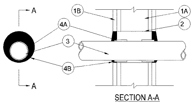
1.Wall Assembly — The 1 or 2 hr fire-rated gypsum board/stud assembly shall be constructed of the materials and in the manner described in the individual U300, U400, V400 or W400 Series Wall and Partition Design in the UL Fire Resistance Directory and shall include the following construction features:
A.Studs — Wall framing may consist of either wood studs or steel channel studs. Wood studs to consist of nom 2 by 4 in (51 by 102 mm) lumber spaced 16 in.(406 mm) OC. Steel studs to be min 3-5/8 in.(92 mm) wide and spaced max 24 in.(610 mm) OC.B.Gypsum Board* — Min 5/8 in. (16 mm) thick. The gypsum board type, thickness, number of layers, fastener type and sheet orientation shall be as specified in the individual Design in the UL Fire Resistance Directory. Max diam of opening is 5 in. (127 mm).The hourly F Rating of the firestop system is equal to the hourly fire rating of the wall assembly in which it is installed
2.Metallic Sleeve — (Optional) Cylindrical sleeve fabricated from min 0.018 in. (0.46 mm) thick (28 gauge) galv sheet steel and having a min 1 in. (25 mm) lap along the longitudinal seam. Sheet steel coiled to a diam less than circular cutouts in wall assembly, inserted through both sides of wall and allowed to uncoil against the circular cutouts in the wall assembly. Sleeve to be installed flush with each surface of the wall assembly.
2A.Metallic Sleeve — (Optional, Not Shown) - As an alternate to Item 2A, steel sleeve may consist of Schedule 5 (or heavier) steel pipe, rigid steel conduit or EMT friction-fitted into wall assembly flush with each surface of the wall assembly.
3.Through Penetrants — One nonmetallic pipe or conduit to be installed either concentrically or eccentricity within the firestop system. The annular space between the pipe or conduit and the periphery of the opening shall be a min 1/4 in. (6 mm) to max 1-1/4 in. (32 mm). Pipe or conduit to be rigidly supported on both sides of wall. The following types and sizes of pipes or conduits may be used:
A.Polyvinyl Chloride (PVC) Pipe — Nom 3 in. (76 mm) diam (or smaller) Schedule 40 solid or cellular core PVC pipe for use in closed (process or supply) or vented (drain, waste, or vent) piping systems.B.Chlorinated Polyvinyl Chloride (CPVC) Pipe — Nom 3 in. diam (76 mm) (or smaller) SDR 13.5 CPVC pipe for use in closed (process or supply).C.Rigid Nonmetallic Conduit+ — Nom 3 in. (76 mm) diam (or smaller) Schedule 40 PVC conduit installed in accordance with the National Electrical Code, (NFPA No. 70).
4.Firestop System — The firestop system shall consist of the following:
A.Fill, Void or Cavity Materials* — Wrap Strip — Nom 1/4 in. (6 mm) thick intumescent material faced on both sides with a plastic film, supplied in 1-1/2 in. (38 mm) wide wrap strips. Single layer of wrap strip wrapped around the through penetrant with ends butted and secured together by means of masking tape. Wrap strip slid into annular space such that the visible ends are recessed 1/4 in. (6 mm) from each surface of the wall.
RECTORSEAL — FlameSafe (TM) Wrap Strip, Metacaulk Wrap Strip or Biostop Wrap StripB.Fill, Void or Cavity Materials* — Sealant — Min 5/8 in. (16 mm) thickness of fill material applied within the annulus flush with both surfaces of wall. Additional fill material to be installed such that a min 3/8 in. (10 mm) thick crown is formed around the through penetrant.
RECTORSEAL — FlameSafe FS1900, FS1901, FS1905, FS1929, Metacaulk 1000, Metacaulk 350i, Biostop 350i or Biostop 500+
*Bearing the UL Classification Marking