W-L-1404
January 30, 2017
January 30, 2017
| ANSI/UL1479 (ASTM E814) | CAN/ULC S115 |
|---|---|
1.Wall Assembly — The fire rated gypsum board/stud wall assembly shall be constructed of the materials and in the manner specified in the individual U300, U400 or V400 Series Wall and Partition Designs in the UL Fire Resistance Directory and shall include the following construction features:
A.Studs — Wall framing may consist of either wood studs or steel channel studs. Wood studs to consist of nom 2 by 4 in.(51 X 102 mm) lumber spaced 16 in.(406 mm) OC. Steel studs to be min 3-1/2 in.(89 mm) wide and spaced max 24 in.(610 mm) OC.B.Gypsum Board* — Min 5/8 in. (16 mm) thick. Thickness, type, number of layers and fasteners as required in the individual Wall and Partition Design. Max diam of opening is 26-3/8 in. (670 mm) Max diam of opening is 14-1/2 in. (368 mm) when wood studs are used.The hourly F Rating of the firestop system is equal to the hourly fire rating of the wall assembly in which it is installed.
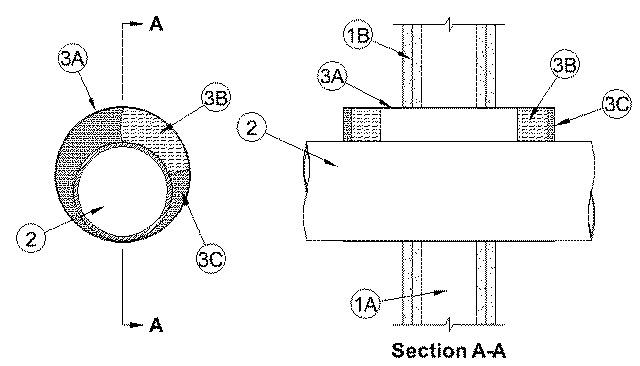
2.Through Penetrants — One metallic pipe, conduit or tube installed concentrically or eccentrically within the firestop system. Annular space to be min 0 in. (point contact) to max 2 in. (51 mm). Pipe, conduit or tubing to be rigidly supported on both sides of wall assembly. The following types and sizes of metallic pipes, conduits or tubing may be used:
A.Steel Pipe — Nom 24 in. (610 mm) diam (or smaller) Schedule 5 (or heavier) steel pipe.B.Iron Pipe — Nom 24 in. (610 mm) diam (or smaller) cast or ductile iron pipe.C.Conduit — Nom 6 in. (152 mm) diam (or smaller) rigid steel conduit, nom 4 in. (102 mm) diam (or smaller) electrical metallic tubing (EMT) or nom 1 in. (25 mm) diam (or smaller) flexible steel conduit.D.Copper Pipe or Tubing — Nom 6 in. (152 mm) diam (or smaller) Regular (or heavier) copper pipe or Type L (or heavier) copper tube.
3.Firestop System — The firestop system shall consist of the following:
A.Metallic Sleeve — A steel sleeve consisting of Schedule 5 (or heavier) steel pipe, rigid steel conduit or EMT friction-fitted into wall assembly flush with or extending a max 4 in. (102 mm) beyond each surface of the wall assembly.A1.Metallic Sleeve — As an alternate to Item 3A, Cylindrical sleeve fabricated from min 0.018 in. (0.46 mm) thick (28 gauge) galv sheet steel and having a min 1 in. (25 mm) lap along the longitudinal seam. Sheet steel coiled to a diam less than circular cutouts in wall assembly, inserted through both sides of wall and allowed to uncoil against the circular cutouts in the wall assembly. Sleeve to be installed flush with or extending max 1 in. (25 mm) beyond each surface of the wall assembly.B.Packing Material — Min 2 in. (51 mm) thickness of nom 4 pcf (64 kg/m3) mineral wool batt insulation tightly-packed into ends of steel sleeve and recessed as required to accommodate required thickness of fill material (Item 3C).C.Fill, Void or Cavity Materials* - Sealant — Min 5/8 in. (16 mm) thickness of fill material applied within annular space flush with edges of steel sleeve on both sides of the wall assembly. Nom 3/8 in. (10 mm) diam bead of fill material to be applied at the point contact location between the metallic penetrant and the steel sleeve. Additional nom 3/8 in. (10 mm) diam bead of fill material applied at the steel sleeve/gypsum board interface when sleeve projects beyond the surface of the wall assembly. When rigid steel sleeve (Item 3A) is used, fill material may be installed flush with both ends of sleeve in walls. When sheet metal sleeve (Item 3A1) is used, fill material to be installed flush with both surfaces of wall within the sleeve.
RECTORSEAL — FlameSafe FS 900+ or FS 1900 Sealant, Metacaulk MC 150+, Biostop BF 150+