W-L-1325
February 20, 2019
February 20, 2019
| ANSI/UL1479 (ASTM E814) | CAN/ULC S115 |
|---|---|
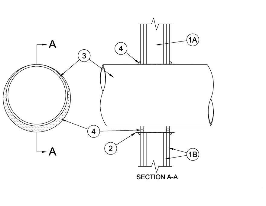
1.Wall Assembly — The 1 or 2 hr fire rated gypsum board/stud wall assembly shall be constructed of the materials and in the manner specified in the individual U300, U400, V400 or W400 Series Wall and Partition Designs in the UL Fire Resistance Directory and shall include the following construction features:
A.Studs — Wall framing may consist of either wood studs or steel channel studs. Wood studs to consist of nom 2 by 4 in. (51 by 102 mm) lumber spaced 16 in. (406 mm) OC. Steel channel studs to be min 3-1/2 in. (89 mm) wide and spaced max 24 in. (610 mm) OC.B.Gypsum Board* — One or two layers of nom 5/8 in. (16 mm) thick gypsum board as specified in the individual Wall and Partition Design. Max diam of opening is 14-1/2 in. (368 mm).The hourly F and FH Ratings of the firestop system are equal to the hourly fire rating of the wall assembly.
2.Steel Sleeve — (Optional) — Max 14 in. (368 mm) diam sleeve fabricated from min 0.018 in. (0.46 mm) thick (28 gauge) galv sheet steel, inserted into opening and allowed to uncoil against the circular cutouts. Sleeve to be installed flush with or extending max 1 in. (25 mm) beyond each surface of the wall assembly.
2A.Steel Sleeve — (Optional) - As an alternate to Item 2, max 12 in. (305 mm) Schedule 5 (or heavier) steel pipe, max 6 in. (152 mm) rigid steel conduit or max 4 in. (102 mm) EMT, friction-fit into wall assembly, flush with or extending a max 4 in. (102 mm) beyond each surface of the floor or wall assembly.
3.Through Penetrants — One metallic pipe, conduit or tubing to be installed concentrically or eccentrically within the firestop system. Pipe, conduit or tubing to be rigidly supported on both sides of wall assembly. The following types and sizes of metallic pipes, conduit or tubing may be used:
A.Steel Pipe — Nom 12 in. (305 mm) diam (or smaller) Schedule 10 (or heavier) steel pipe. An annular space of min 0 in. (point contact) to max 1-3/4 in. (44 mm) is required within the firestop system.B.Iron Pipe — Nom 12 in. (305 mm) diam (or smaller) Schedule 10 (or heavier) cast iron pipe. An annular space of min 0 in. (point contact) to max 1-3/4 in. (44 mm) is required within the firestop system.C.Copper Tubing — Nom 4 in. (102 mm) diam (or smaller) Type L (or heavier) copper tube. An annular space of min 0 in. (point contact) to max 1-7/8 in. (48 mm) is required within the firestop system.D.Copper Pipe — Nom 4 in. (102 mm) diam (or smaller) Regular (or heavier) copper pipe. An annular space of min 0 in. (point contact) to max 1-7/8 in.(48 mm) is required within the firestop system.E.Conduit — Nom 6 in. (152 mm) diam (or smaller) steel conduit or nom 4 in. (102 mm) diam (or smaller) steel electrical metallic conduit. An annular space of 0 in. (point contact) to 1-7/8 in. is required within the firestop system.
4.Fill Void or Cavity Materials* - Caulk — Min 1/2 in. (13 mm) thickness of fill material applied within the annulus on both surfaces of the wall assembly. When steel sleeve is not used or when steel sleeve is flush with the wall surfaces, a min 1/2 in. (13 mm) diam bead of caulk shall be applied to the penetrant /gypsum board interface at the point contact location on both sides of wall. When steel sleeve is used, a bead of caulk is applied to the steel sleeve/gypsum board interface on both sides of wall. When sheet metal sleeve (Item 2) is used, fill material to be installed flush with both surfaces of wall within the sleeve. When rigid steel sleeve (Item 2A) is used, fill material may be installed flush with both ends of sleeve in walls.
RECTORSEAL — Metacaulk MC 150+, Metacaulk 1000