W-L-1253
December 28, 2023
December 28, 2023
M Rating (Movement) — See Table 1
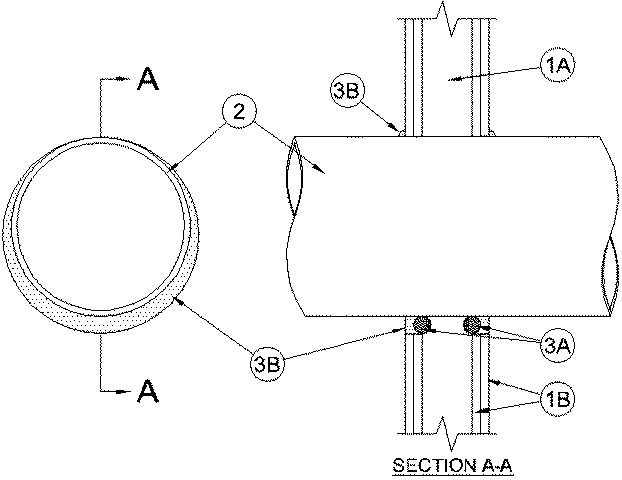
1.Wall Assembly — The 1 or 2 hr fire rated gypsum board/stud wall assembly shall be constructed of the materials and in the manner specified in the individual U300, U400, V400 or W400Series Wall and Partition Designs in the UL Fire Resistance Directory and shall include the following construction features:A.Studs — Wall framing consists of steel channel studs Steel studs to be min 3-1/2 in. (89 mm) wide and spaced max 24 in. (610 mm) OC.B.Gypsum Board* — One or two layers of nom 5/8 in. thick gypsum wallboard as specified in the individual Wall and Partition Design. Max diam of opening is 14 in. (356 mm)The hourly F Rating of the firestop system is equal to the hourly fire rating of the wall assembly.
2.Through Penetrants — One metallic pipe, conduit or tubing to be installed concentrically or eccentrically within the firestop system. Pipe or tubing to be rigidly supported on both sides of wall assembly. The following types and sizes of metallic pipes or tubing may be used:A.Steel Pipe — Nom 12 in. (305 mm) diam (or smaller) Schedule 10 (or heavier) steel pipe. A nom annular space of 0 (point contact) to 1-1/4 in. (32 mm) is required within the firestop system.B.Iron Pipe — Nom 12 in. (305 mm) diam (or smaller) Schedule 10 (or heavier) cast iron pipe. A nom annular space of 0 (point contact) to 1-1/4 in. (32 mm) is required within the firestop system.C.Copper Tubing — Nom 4 in (102 mm) diam (or smaller) Type L (or heavier) copper tube. A nom annular space of 0 (point contact) to 1 in. (25.4 mm) is required within the firestop system.D.Copper Pipe — Nom 4 in. (102mm) diam (or smaller) Regular (or heavier) copper pipe. A nom annular space of 0 (point contact) to 1 in. (25.4 mm) is required within the firestop system.E.Conduit — Nom 6 in. (152 mm) (or smaller) steel conduit or nom 4 in. (102 mm) diam (or smaller) steel electrical metallic conduit A nom annular space of 0 (point contact) to 1 in. (25.4 mm) is required within the firestop system.
3.Firestop System — The firestop system shall consist of the following:A.Packing Material — (Optional) In 2 hr wall assemblies, foam backer rod firmly packed into opening as a permanent form. Packing material to be recessed from each surface of the wall to accommodate the required thickness of fill material.B.Fill Void or Cavity Materials* - Caulk — Min 5/8 in. (16 mm) thickness of fill material applied within the annulus on both surfaces of the wall assembly. A min 1/2 in. (13 mm) diam bead of caulk shall be applied to the pipe/gypsum board interface at the point contact location on both sides of wall.
RECTORSEAL — MC 150+ CaulkThe M Rating for the firestop system is dependent on the variables as noted in the Table 1 below.
Table 1
Movement
Direction
Penetrant
ItemNominal
Penetrant
Diameter
Annular
Space
Movement
Sealant
Depth
F
Rating
L
RatingY
2A, 2B, 2E
2 in. (52 mm)
Max 1 in. (25.4 mm)
5%
5/8 in. (16 mm)
2 hr
N/A
Z
2A, 2B, 2E
2 in. (52 mm)
1 in. (25.4 mm)
0.25 in. (6mm)
5/8 in. (16 mm)
2 hr
N/A