W-L-1207
July 16, 2014
July 16, 2014
| ANSI/UL1479 (ASTM E814) | CAN/ULC S115 |
|---|---|
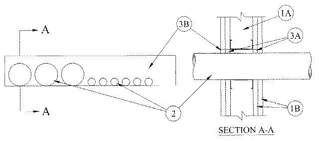
1.Wall Assembly — The 1 or 2 hr fire-rated gypsum board/stud wall assembly shall be constructed of the materials and in the manner described in the individual U300, U400 or V400 Series Wall and Partition Design in the UL Fire Resistance Directory and shall include the following construction features:
A.Studs — Wall framing may consist of either wood studs or steel channel studs. Wood studs to consist of nom 2 by 4 in. (51 by 102 mm) lumber spaced 16 in. (406 mm) OC. Steel studs to be min 3-5/8 in. (92 mm) wide and spaced max 24 in. (610 mm) OC. Additional framing members to be installed in stud cavity containing the through penetrants to form a rectangular box around the through penetrants.B.Gypsum Board* — /8 in. (16 mm) thick, 4 ft (1.2 m) wide with square or tapered edges. The gypsum board type, thickness, number of layers, fastener type and sheet orientation shall be as specified in the individual U300 or U400 Series Design in the UL Fire Resistance Directory. Max area of opening is 90-1/2 sq in. (584 cm2) with max dimensions of 22-5/8 in. (575 mm) for steel stud walls. Max area of opening is 58 sq in. (374 cm2) with max dimensions of 14-1/2 in. (368 mm) for wood stud walls.The hourly F Rating of the firestop system is equal to the hourly fire rating of the wall assembly in which it is installed.
2.Through Penetrants — One or more through penetrants to be installed within the opening. Only three through penetrants shall have a nom diam greater than 1 in. (25 mm). The space between the through penetrants shall be a nom 1/2 in. (13 mm). The annular space between through penetrants and periphery of opening shall be min 0 in. (point contact) to max 1/2 in. (13 mm) for through penetrants having a nom diam greater than 1 in. (25 mm). The annular space between through penetrants and periphery of opening shall be min 0 in. (point contact) to max 2-7/8 in. (73 mm) for through penetrants having a nom diam 1 in. (25 mm) or less. The through penetrants to be rigidly supported on both sides of wall assembly. The following types and sizes of through penetrants may be used:
A.Steel Pipe — Nom 3 in. (76 mm) diam (or smaller) Schedule 10 (or heavier) steel pipe.B.Iron Pipe — Nom 3 in. (76 mm) diam (or smaller) cast or ductile iron pipe.C.Conduit — Nom 3 in. (76 mm) diam (or smaller) steel electrical metallic tubing or galv steel conduit.
3.Firestop System — The firestop system shall consist of the following:
A.Forms — (Optional) Used to prevent the leakage of fill material during installation in 2 hr fire-rated assemblies. Forms to be rigid sheet material or polyurethane backer rod, cut to fit the contour of the through penetrant and friction fitted into the opening on both sides of wall. Forms to be recessed from both surfaces of wall to accommodate the required thickness of fill material.B.Fill, Void or Cavity Material* — Sealant — Min 5/8 in. (16 mm) thickness of fill material applied within annulus, flush with both surfaces of wall. At the point contact location between through penetrants and gypsum board, a min 3/8 in. (10 mm) diam bead of fill material shall be applied at the gypsum board/through penetrant interface on both surfaces of wall.
RECTORSEAL — FS900+, FS929+, FS901+CG, FS905+CG and FS955+CG, Metacaulk MC 150+, Biostop BF 150+