W-L-1118
May 13, 2004
May 13, 2004
F Rating — 2 Hr
T Rating — 0 Hr
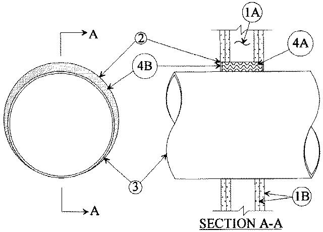
1.Wall Assembly — The fire-rated gypsum wallboard/stud wall assembly shall be constructed of the materials and in the manner specified in the individual U300 or U400 Series Wall and Partition Designs in the UL Fire Resistance Directory and shall include the following construction features:
A.Studs — Wall framing may consist of either wood studs or steel channel studs. Wood studs to consist of nom 2 by 4 in. lumber spaced 16 in. OC. Steel studs to be min 2-1/2 in. wide and spaced max 24 in. OC. The opening in the wall to accommodate the through penetrant (Item 2) shall be framed on all sides within the stud cavity using short lengths of stud installed between the vertical stud members.B.Gypsum Board* — Two layers of nom 5/8 in. thick gypsum wallboard, as specified in the individual Wall and Partition Design. Max diam of opening is 22 in. for steel stud walls. Max diam of opening is 14-1/2 in. for wood stud walls.
2.Steel Wire Mesh — Cylindrical sleeve fabricated from No. 8 steel wire mesh and having a min 1 in. lap along the longitudinal seam. Length of steel wire mesh to be 1/2 in. less than thickness of the wall. Steel wire mesh to be centered and formed to fit periphery of through opening.
2A.Metallic Sleeve — (Optional) — Cylindrical sleeve fabricated from min No. 26 gauge galv sheet steel and having a min 1 in. overlap along the longitudinal seam. Ends of sleeve to be flush with or extend a max 1 in. beyond each surface of wall.
3.Through Penetrants — One metallic pipe, conduit or tubing to be installed either concentrically or eccentrically within the firestop system. The annular space between pipe, conduit or tubing and periphery of opening shall be min 0 in. (point contact) and max 2 in. Pipe, conduit or tubing to be rigidly supported on both sides of wall assembly. The following types and sizes of metallic pipes, conduits or tubing may be used:
A.Steel Pipe — Nom 20 in diam (or smaller) Schedule 10 (or heavier) steel pipe.B.Iron Pipe — Nom 20 in diam (or smaller) cast or ductile iron pipe.C.Conduit — Nom 4 in. diam (or smaller) electrical metallic tubing or steel conduit.D.Copper Tubing — Nom 4 in. diam (or smaller) Type L (or heavier) copper tubing.E.Copper Pipe — Nom 4 in. diam (or smaller) Regular (or heavier) copper pipe.
4.Firestop System — The firestop system shall consist of the following:
A.Packing Material — Min 4-1/2 in. thickness of min 4.0 pcf mineral wool batt insulation firmly packed into opening as a permanent form. Packing material to be recessed from both surfaces of wall as required to accommodate the required thickness of fill material.B.Fill, Void or Cavity Material* — Caulk — Min 1/4 in. thickness of fill material applied within the annulus, flush with both surfaces of wall. At the point contact location between pipe and wall, a min 1/4 in. diam bead of fill material shall be applied at the wall/pipe interface on both surfaces of wall.
RECTORSEAL — Metacaulk 1000