W-J-8061
June 8, 2017
June 8, 2017
| ANSI/UL1479 (ASTM E814) | CAN/ULC S115 |
|---|---|

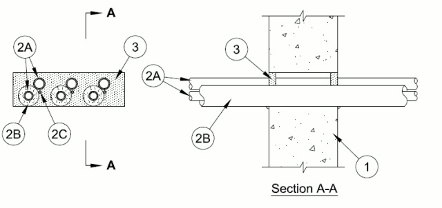
1.Wall Assembly — Min 6 in. thick reinforced lightweight or normal weight (100-150 pcf) concrete. Wall may also be constructed of any UL Classified Concrete Blocks*. Max area of opening is 30 in. with a max dimension of 10 in.
See Concrete Blocks (CAZT) in the Fire Resistance Directory for names of manufacturers.
2.Air Conditioning (AC) Line Set — One or more AC line sets installed eccentrically or concentrically within opening. Each AC line set consists of two pipes or tubes (Item 2A), tubing insulation (Item 2B) and a thermostat cable (Item 2C). The space between the AC line sets shall be min 1/2 in. to max 3/4 in. The space between the AC line sets and the periphery of the opening shall be min 0 in. (point contact) to max 1 in.
2A.Through Penetrant — A max of two pipes or tubes to be installed in each AC line set. Of the two pipes or tubes, only one may have a nom diam greater than 1/2 in. Annular space between pipes or tubing and periphery of opening shall be min 0 in. (point contact) to max 1-1/2 in. Pipes or tubing to be rigidly supported on both sides of the wall assembly. The following types and sizes of through penetrants may be used:
A.Steel Pipe — Nom 1 in. diam (or smaller) Schedule 5 (or heavier) steel pipe.B.Iron Pipe — Nom 1 in. diam (or smaller) cast or ductile iron pipe.C.Copper Pipe — Nom 1 in. diam (or smaller) Regular (or heavier) copper pipe.D.Copper Tube — Nom 1 in. diam (or smaller) Type L (or heavier) copper tube.
2B.Tube Insulation - Plastics# — Nom 3/4 in. thick acrylonitrile butadiene/polyvinyl chloride (AB/PVC) flexible foam furnished in the form of tubing. The tube insulation may be installed on one max 1/2 in. diam pipe or tube in each AC line set. The annular space between the penetrating item and the periphery of the opening shall be min 0 in. (point contact) to max 1/2 in. The space between the pipes or tubing within each AC line set shall be 0 in. (point contact).
See Plastics (QMFZ2) category in the Plastics Recognized Component Directory for names of manufacturers. Any Recognized Component tube insulation meeting the above specifications and having a UL 94 Flammability Classification of 94-5VA may be used.
2C.Cable — One 4 pair No. 18 AWG (or smaller) thermostat cable with polyvinyl chloride (PVC) insulation and jacket materials may be installed with each AC line set. Cable to be spaced min 0 in. (point contact) to max 1/2 in. from the other penetrants in each line set. The space between the cable and the periphery of the opening shall be min 0 in. (point contact) to max 1/2 in. Cable to be rigidly supported on both sides of wall assembly.
3.Fill, Void or Cavity Material* Sealant — Min 5/8 in. thickness of fill material applied with annulus, flush with both surfaces of wall assembly. At point contact location, min 1/4 in. diam bead of fill material applied at through penetrant/concrete interface on both surfaces of wall. Additional fill material forced into grouped penetrant interstices to max extent possible.
RECTORSEAL — Metacaulk 1000, Metacaulk 350i, Metacaulk MC 150+, Biostop 500+, Biostop 350i, Biostop BF 150+, FlameSafe1900 or FlameSafe900+
# Bearing the UL Recognized Component Marking