W-J-6004
January 8, 2010
January 8, 2010
F Rating — 2 Hr
T Rating — 1 Hr
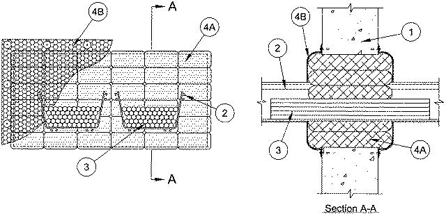
1.Wall Assembly — Min 6 in. thick reinforced lightweight or normal weight (100-150 pcf) concrete. Wall may also be constructed of any UL Classified Concrete Blocks*. Max size of opening is 384 sq in. with a max dimension of 32 in.
See Concrete Blocks (CAZT) category in the Fire Resistance Directory for names of manufacturers.
2.Cable Trough+ — Nom 12 in. wide by 4 in. deep telecommunication cable trough formed from min 0.105 in. thick acrylonitrile butadiene styrene (ABS). A max of two cable troughs to be installed in the opening. The annular space between the cable trough and the periphery of the framed opening shall be min 1 in. to max 6-1/2 in. The nom annular space between the cable troughs shall be a nom 1 in. Cable trough to be rigidly supported on both side of the wall assembly.
3.Cables — Aggregate cross-sectional area of cables in cable trough not to exceed 40 percent of the cross-sectional area of the cable trough. Any combination of the following types and sizes of cables may be used:
A.Max 72 fibers - 62.5/125 fiber optic cable with polyvinyl chloride (PVC) insulation and jacket materials. B.Max RG/U (or smaller) coaxial copper conductor cable with fluorinated ethylene insulation and PVC jacket materials.
4.Firestop System — The firestop system shall consist of the following:
A.Fill, Void or Cavity Materials* — Bags — Nom 13-1/2 in. long by 7 in. wide by 1/2 to 1-1/2 in. thick fabric covered intumescent bags. Bags to be tightly packed between cables and periphery of framed opening and between cable troughs and periphery of framed opening. Bags to be installed with 7 in. dimension projecting through and centered within the opening.
RECTORSEAL — FlameSafe BagsB.Wire Lath — Nom 1 in. diamond shaped wire lath fabricated from min No. 20 AWG galv steel wire. Wire lath cut to fit the contour of the opening with a min 3 in. lap beyond the periphery of the opening. Wire lath secured to framing members on both surfaces of wall assembly by means of 1/4 in. diam by 1-3/4 in. long steel concrete anchors in conjunction with 1/4 in. by 1-1/2 in. diam steel fender washers, spaced 6 in. OC. The joints within the wire lath shall overlap a min of 2 in. and be secured together by means of No. 20 AWG steel wire spaced 4 in. OC.
+ Bearing the UL Listing Mark