February 5, 2014
| ANSI/UL1479 (ASTM E814) | CAN/ULC S115 |
|---|---|
1.Wall Assembly — Min 4-7/8 in. (124 mm) and 6-1/8 in. (156 mm) thick lightweight or normal weight (100-150 pcf or 1600-2400 kg/m3) concrete for 1 and 2 hr rated assemblies, respectively. Wall may also be constructed of any UL Classified Concrete Blocks*. Max diam of opening is 14 in. (356 mm).
See Concrete Blocks (CAZT) category in the Fire Resistance Directory for names of manufacturers.
The hourly T, FT and FTH Ratings are 3/4 hr and 1-1/2 hr for 1 and 2 hr rated assemblies, respectively.
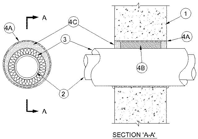
2.Through Penetrants — One metallic pipe or tube installed concentrically or eccentrically within the firestop system. Pipe or tube to be rigidly supported on both sides of the wall. The following types and sizes of through penetrants may be used:
A.Steel Pipe — Nom 6 in. (152 mm) diam (or smaller) Schedule 10 (or heavier) steel pipe.B.Iron Pipe — Nom 6 in. (152 mm) diam (or smaller) cast or ductile iron pipe.C.Copper Tubing — Nom 6 in. (152 mm) diam (or smaller) Type L (or heavier) copper tubing.D.Copper Pipe — Nom 6 in. (152 mm) diam (or smaller) Regular (or heavier) copper pipe.E.Conduit — Nom 4 in. (102 mm) diam (or smaller) steel electrical metallic tubing (EMT) or nom 6 in. (152 mm) diam (or smaller) steel conduit.
3.Pipe Covering* — One of the following types of pipe coverings shall be used:
A.Pipe and Equipment Covering Materials* — Nom 3 in. (76 mm) thick hollow cylindrical heavy density (min 3.5 pcf or 56 kg/m3) glass fiber units jacketed on the outside with an all service jacket. Longitudinal joints sealed with metal fasteners or factory-applied self-sealing lap tape. Transverse joints secured with metal fasteners or butt tape supplied with the product. The annular space between the insulated through penetrant and the metallic sleeve (Item 4A) shall be min 0 in. (point contact) to max 1-7/8 in. (48 mm).See Pipe and Equipment Covering Materials* (BRGU) category in the Building Materials Directory for names of manufacturers. Any pipe covering material meeting the above specifications and bearing the UL Classification Marking with a Flame Spread Index of 25 or less and a Smoke Developed Index of 50 or less may be used.
B.Pipe and Equipment Covering Materials* — Nom 3 in. (76 mm) thick unfaced mineral fiber pipe insulation having a nom density of 3.5 pcf (56 kg/m3) (or heavier) and sized to the outside diam of the pipe or tube. Pipe insulation secured with min 8 AWG steel wire spaced 12 in. OC (305 mm). The annular space between insulated penetrating item and the metallic sleeve (Item 4A) shall be min 0 in. (point contact) to max 1-7/8 in. (48 mm).C.Sheathing Material* — Used in conjunction with Item 3B. Foil-scrim-kraft or all service jacket material shall be wrapped around the outer circumference of the pipe insulation (Item 3B) with the kraft side exposed. Longitudinal and transverse joints sealed with metal fasteners or butt tape.See Sheathing Materials* (BVDV) category in the Building Materials Directory for names of manufacturers. Any sheathing material meeting the above specifications and bearing the UL Classification Marking with a Flame Spread Index of 25 or less and a Smoke Developed Index of 50 or less may be used.
4.Firestop System — The firestop system shall consist of the following:
A.Metallic Sleeve — Cylindrical sleeve fabricated from min 0.018 in. (0.46 mm) thick (No. 28 gauge) galv sheet steel and having a min 1 in. (25 mm) lap along the longitudinal seam. Length of steel sleeve to be equal to thickness of wall. The inside diam of sleeve shall be min 1 in. (25 mm) larger than the outside diam of pipe covering. Sleeve installed by coiling the sheet steel to a diam smaller than the through opening in the concrete or block wall, inserting the coil through the opening and releasing the coil to let it uncoil against the circular wall opening. Sleeve to be tightly fitted in wall opening with no annular space. The annular space between the insulated through penetrant and the sleeve shall be min 0 in. (point of contact) to max 1-7/8 in. (48 mm).B.Packing Material — Nom 3 or 4 in. (76 or 102 mm) thickness of min 4.0 pcf (64 kg/m3) mineral wool batt insulation, for 1 and 2 hr rated wall, respectively, firmly packed into the opening as a permanent form. Packing material to be recessed from both surfaces of wall to accommodate the required thickness of fill material.C.Fill, Void or Cavity Material* - Sealant — Min 1 in. (25 mm) thickness of fill material applied within annulus, flush with each surface of wall. At point contact location, a min 3/8 in. (10 mm) bead of fill material shall be applied to the wall/sleeve/pipe covering interface on both surfaces of the wall.
RECTORSEAL — FlameSafe® FS1900, Metacaulk 1000, Metacaulk 350i, Biostop 350i or Biostop 500+