W-J-5036
March 23, 2016
March 23, 2016
| ANSI/UL1479 (ASTM E814) | CAN/ULC S115 |
|---|---|
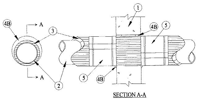
1.Wall Assembly — Min 6 in. (152 mm) thick reinforced lightweight or normal weight (100-150 pcf or 1600-2400 kg/m3 ) concrete. Wall may also be constructed of any UL Classified Concrete Blocks*. Max diam of opening is 18 in. (457 mm).See Concrete Block (CAZT) category in the Fire Resistance Directory for names of manufacturers.
2.Through Penetrant — One metallic pipe to be installed either concentrically or eccentrically within the firestop system. Pipe to be rigidly supported on both sides of wall assembly. The following types and sizes of metallic pipes may be used:
A.Steel Pipe — Nom 10 in. (254 mm) diam (or smaller) Schedule 10 (or heavier) steel pipe.B.Iron Pipe — Nom 10 in. (254 mm) diam (or smaller) cast or ductile iron pipe.C.Copper Tubing — Nom 6 in. (152 mm) diam (or smaller) Type L (or heavier) copper tubing.
Penetrant Diam/Type F Rating Hr T Rating Hr Sealant 10 in. (254 mm) steel and iron 2 1-1/2 FS1900 Series 6 in. (152 mm) copper, steel or iron 2 1 FS 900+
3.Through Penetrating Product* — Cellular Glass Insulation — Nom 3 in. (76 mm) thick cellular glass units sized to the outside diam of the through-penetrant and supplied in nom 24 in. (610 mm) long half sections or nom 18 in. (457 mm) long segments. Pipe insulation installed on pipe in accordance with the manufacturer's instructions. The annular space between insulated pipe and periphery of opening shall be min 0 in. (point contact) to max 1-1/4 in. (32 mm).
4.Firestop System — The firestop system shall consist of the following:
A.Forms — (Not Shown) — Used to prevent the leakage of fill material during installation is 2 hr fire-rated assemblies. Forms to be rigid sheet material or polyurethane backer rod, cut to fit the contour of the insulated through penetrant and friction fitted into the opening on both sides of wall. Forms to be recessed from both surfaces of wall to accommodate the required thickness of fill material.B.Fill, Void or Cavity Materials* — Sealant — Min 5/8 in. (16 mm) thickness of fill material applied within the annulus flush with both surfaces of wall. After installation of the metal jacket (Item 5), min 3/8 in. (10 mm) diam bead of fill material shall be applied to the metal jacketing/fill material interface on both sides of wall.
RECTORSEAL — FlameSafe FS 900+, FS1900, FS1901, FS1905, FS1929, Metacaulk MC 150+, Metacaulk 1000, Metacaulk 350i, Biostop BF 150+, Biostop 350i or Biostop 500+
5.Metal Jacket — (Not required for FS900+) — Min 12 in. (305 mm) long jacket formed of min 0.010 in. (0.25 mm) thick aluminum sheet cut to wrap tightly around the pipe insulation with a min 2 in. (51 mm) lap and secured using 1/2 in. (13 mm) wide by 0.028 in. (0.7 mm) thick stainless steel hose clamps. Clamps to be located within 2 in. (51 mm) of each end of the jacket and spaced max 10 in. (254 mm) OC. Jacket to be installed with edge abutting surface of fill material (Item 4B) on each side of wall. Metal jacket to be used in addition to any other jacketing material which may be required or desired on the pipe insulation.