W-J-3113
January 30, 2017
January 30, 2017
| ANSI/UL1479 (ASTM E814) | CAN/ULC S115 |
|---|---|
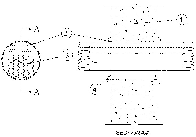
1.Wall Assembly — Min 6 in. (152 mm) thick reinforced lightweight or normal weight (100-150 pcf or 1600-2400 kg/m3) concrete. Wall may also be constructed of any UL Classified Concrete Blocks*. Max diam of opening is 4 in. (9102 mm).
See Concrete Blocks (CAZT) category in the Fire Resistance Directory for names of manufacturers.
2.Steel Sleeve — (Optional) — Max 4 in. (102 mm) diam sleeve fabricated from min 0.018 in. (0.46 mm) thick (28 gauge) galv sheet steel and floor or wall assembly, inserted opening and allowed to uncoil against the circular cutouts. Sleeve to be installed flush with or extending max 1 in. (25 mm) beyond each surface of the wall assembly.
2A.Steel Sleeve — (Optional) - As an alternate to Item 2, max 4 in. (102 mm) Schedule 5 (or heavier) steel pipe rigid steel conduit or EMT, cast or grouted into wall assembly, flush with or extending a max 4 in. (102 mm) beyond each surface of the floor or wall assembly.
When steel sleeve is used, T, FT and FTH Ratings are 0 hr.
3.Cables — Aggregate cross-sectional area of cables to be min 25 percent to max 64 percent of the aggregate cross-sectional area of the opening. Cables to be tightly bundled and rigidly supported on both sides of wall assembly. The annular space between the cables and the periphery of opening shall be min 0 in. (point contact) to max 2 in. (51mm). Any combination of following types and sizes of copper conductor cables may be used:
A.Max 2/C with ground, No. 12 AWG MC (BX) cable with polyvinyl chloride (PVC) insulation on conductors inside a steel armored jacket. B.Max 3/C with ground, No. 12 AWG (or smaller) nonmetallic sheathed (Romex) cable with copper conductors, PVC insulation and jacket. C.Max 8/C No. 12 AWG (or smaller) Type SOW-A P-123-70-MSHA. D.Max 25 pair, No. 24 AWG (or smaller) copper conductor telephone cable with XLPE/PVC insulation, with or without PVC jacket. E.Max RG6 (or smaller) television coaxial cable CATVX. F.Max 4 pair, No. 24 AWG (or smaller) copper conductor data cable with Hylar insulation and jacketing. G.Max 1/C, No. 18 AWG (or smaller) Type MTW or THHN or THWN or gas & oil res II 600V (UL) or AWM VW-1 power cable. H.Max 1/C, No. 14 AWG (or smaller) Type MTW or THHN or THWN or gas & oil res II 600V (UL) or AWM VW-1 power cable. I.Max 1/C, No. 10 AWG (or smaller) Type THHN or THWN gasoline & oil resistant II 600V VW-1 E116364 (UL) power cable. J.Optical Fiber Cable max 62.5/125 Type UFNR. K.Max 3/C, No. 4/0 with ground, AWG aluminum Triple E Alloy AA8176 Type SE cable Style U Type XHH-W-2 CDRS E32071 (UL) service entrance cable. L.Max 3/C, No. 18 AWG with ground and shield E120910.
4.Firestop System — The firestop system shall consist of the following:
A.Fill, Void or Cavity Material* - Caulk — Min 1/2 in. (51 mm) thickness of fill material applied within the annulus, flush with both surfaces of wall. When steel sleeve is not used or when steel sleeve is flush with the wall surfaces, a min 1/4 in. (6 mm) diam bead of caulk shall be applied at interface of cables and periphery of opening at point contact location on both surfaces of wall. When steel sleeve is used, a bead of caulk is applied to the steel sleeve/concrete interface on both sides of wall. When sheet metal sleeve (Item 2) is used, fill material to be installed flush with both surfaces of wall within the sleeve. When rigid steel sleeve (Item 2A) is used, fill material may be installed flush with both ends of sleeve in walls.
RECTORSEAL — MC 150+, Metacaulk 1000