W-J-3058
December 3, 1999
December 3, 1999
F Rating — 2 Hr
T Ratings — 1-1/4 and 2 Hr (See Item 5)
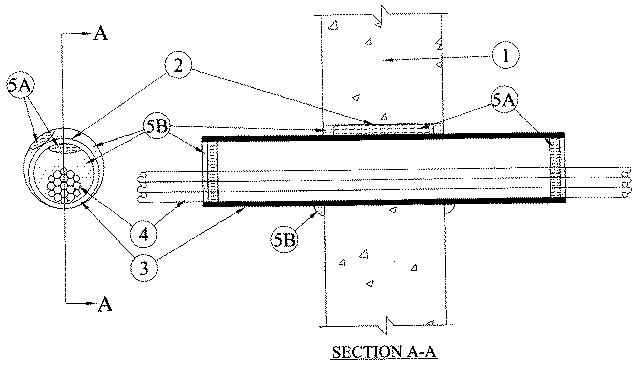
1.Wall Assembly — Min 6 in. thick reinforced lightweight or normal weight (100-150 pcf) concrete. Wall may also be constructed of any UL Classified Concrete Blocks*. Max diam of opening is 4 in.
See Concrete Blocks (CAZT) category in the Fire Resistance Directory for names of manufacturers.
2.Steel Wire Mesh — Cylindrical sleeve fabricated from No. 8 steel wire mesh and having a min 2 in. lap along the longitudinal seam. Length of steel mesh to be 1/2 in. less than thickness of wall. Steel wire mesh to be centered and formed to fit periphery of through opening.
3.Nonmetallic Sleeve — Nom 3 in. diam (or smaller) Schedule 40 solid core polyvinyl chloride pipe. Sleeve installed to project 6 in. beyond each surface of wall. The annular space between nonmetallic sleeve and periphery of opening shall be min 0 in. (point contact) to max 1/2 in.
4.Cables — Aggregate cross-sectional area of bundled cables to be max 24 percent of the cross-sectional area within the nonmetallic sleeve (Item 3). Cables to be rigidly supported on both sides of wall assembly. Any combination of the following types and sizes of copper conductor cables may be used:
A.Max 25 pr No. 24 AWG telephone cables with polyvinyl chloride (PVC) insulation and jacket. B.Max 4 pr No. 24 AWG telephone cables with PVC insulation and jacket. C.Max 2/C with ground No. 12 AWG Type NM nonmetallic sheathed (Romex) cable with PVC insulation and jacket. D.Max 4 pr No. 24 AWG Category 5 computer cables.
5.Firestop System — The firestop system shall consist of the following:
A.Packing Material — Min 5 in. thickness of min 4 pcf mineral wool batt insulation firmly packed into opening around outside of sleeve as a permanent form. Min 1 in. thickness of min 4 pcf mineral wool batt insulation also packed within each end of nonmetallic sleeve around cable bundle as a permanent form. Packing material to be recessed from both surfaces of wall and ends of sleeve as required to accommodate the required thickness of fill material.B.Fill, Void or Cavity Materials* — Caulk — Min 1/2 in. thickness of fill material applied within the annulus around outside of sleeve, flush with both surfaces of wall. Min 1/4 in. thickness of fill material also applied within each end of nonmetallic sleeve around cable bundle, flush with end of sleeve. At point contact locations, a min 1/4 in. diam bead of fill material shall be applied to the wall/nonmetallic sleeve and nonmetallic sleeve/cable interfaces on both sides of wall.
RECTORSEAL — Metacaulk 1000C.Packing Material — (Not Shown) — As an alternate to the steel wire mesh (Item 2) and the mineral wool batt insulation (Item 5A), foam backer rod may be packed into the opening around outside of sleeve and within each end of nonmetallic sleeve around cable bundle as a permanent form. Packing material to be recessed from both surfaces of wall and ends of sleeve as required to accommodate the required thickness of fill material. When foam backer rod is used, the T Rating is 1-1/4 hr. When the steel wire mesh and mineral wool batt insulation are used, the T Rating is 2 hr.