F-E-1005
July 15, 2014
July 15, 2014
| ANSI/UL1479 (ASTM E814) | CAN/ULC S115 |
|---|---|
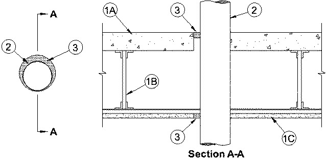
1.Floor-Ceiling Assembly — The 1 hr fire-rated concrete and steel joist Floor-Ceiling assembly shall be constructed of the materials and in the manner described in the individual G500 Series Design in the UL Fire Resistance Directory, as summarized below:
A.Concrete Floor — Normal weight or lightweight (100-150 pcf or 1600-2400 kg/m3) concrete over metal lath or steel deck as specified in the individual G500 Series Design. Max diam of floor opening is 5 in. (127 mm).B.Joists — Steel joists or Structural Steel Members* as specified in the individual G500 Series Design.C.Gypsum Board* — Min 5/8 in. (16 mm) thick, screw-attached to furring channels as specified in the individual G500 Series Design. Max diam of ceiling is 5 in. (127 mm).
2.Through Penetrant — One metallic pipe, conduit or tube to be installed either concentrically or eccentrically within the opening. Penetrant to be located approx midway between joists and rigidly supported on both sides of floor-ceiling assembly. The space between pipes, conduits or tubing and periphery of opening is dependent upon the type of penetrant within the firestop system. The following types and sizes of metallic pipe, conduit or tubing may be used:
A.Steel Pipe — Nom 4 in. (102 mm) diam (or smaller) Schedule 10 (or heavier) steel pipe. The annular space within the firestop system shall be a 0 in. (point contact) to max 1/2 in. (13 mm).B.Iron Pipe — Nom 4 in. (102 mm) diam (or smaller) cast or ductile iron pipe. The annular space within the firestop system shall be a 0 in. (point contact) to max 1/2 in. (13 mm).C.Conduit — Nom 4 in. (102 mm) diam (or smaller) steel electrical metallic tubing or rigid galv steel conduit. The annular space within the firestop system shall be a 0 in. (point contact) to max 1/2 in. (13 mm).D.Copper Tubing — Nom 3 in. (76 mm) diam (or smaller) Type L (or heavier) copper tubing. The annular space within the firestop system shall be a 0 in. (point contact) to max 7/8 in. (22 mm).E.Copper Pipe — Nom 3 in. (76 mm) diam (or smaller) Regular (or heavier) copper pipe. The annular space within the firestop system shall be a 0 in. (point contact) to max 7/8 in. (22 mm).
3.Fill, Void or Cavity Materials* — Sealant — Min 3/4 in. (19 mm) thickness of fill material applied within the annulus, flush with top surface of floor. Min 5/8 in. (16 mm) thickness of fill material applied within the annulus, flush with bottom surface of ceiling. At point contact locations, min 1/4 in. (6 mm) diam bead of fill material applied at penetrant/concrete interface on top surface of floor and penetrant/gypsum board interface on bottom surface of ceiling.
RECTORSEAL — FlameSafe FS 900+, FS 1900, Metacaulk MC 150+, Metacaulk 1000, Metacaulk 350i, Biostop BF 150+, Biostop 350i or Biostop 500+