F-C-7040
July 16, 2015
July 16, 2015
| ANSI/UL1479 (ASTM E814) | CAN/ULC S115 |
|---|---|
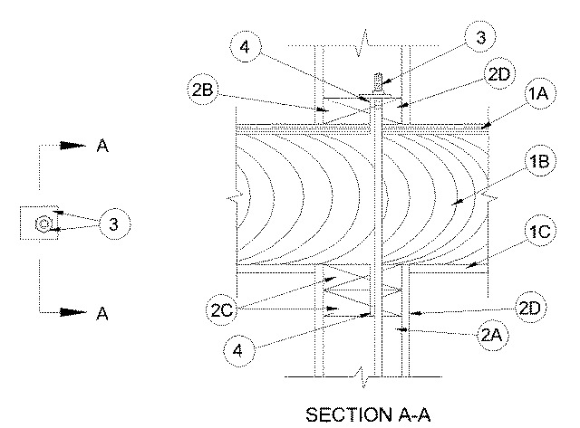
1.Floor-Ceiling Assembly — The 1 hr fire-rated wood joist floor-ceiling assembly shall be constructed of the materials and in the manner specified in the individual L500 Designs in the UL Fire Resistance Directory, as summarized below:
A.Flooring System — Lumber or plywood subfloor with finish floor of lumber, plywood or Floor Topping Mixture* as specified in the individual Floor-Ceiling Design. Max diam of floor opening is 2 in. (51 mm).B.Wood Joists — Nom 10 in. (254 mm) deep (or deeper) lumber, steel or combination lumber and steel joists, trusses or Structural Wood Members* with bridging as required and with ends firestopped.C.Gypsum Board* — Nom 5/8 in. (16 mm) thick as specified in the individual Floor-Ceiling Design. Gypsum board secured to joists as specified in the individual Floor-Ceiling Design.
2.Chase Wall — The through penetrant (Item 3) shall be routed through a 1 hr fire-rated single, double or staggered wood stud/gypsum board chase wall constructed of the materials and in the manner specified in the individual U300 Series Wall and Partition Designs in the UL Fire Resistance Directory and shall include the following construction features:
A.Studs — Nom 2 by 6 in. (51 by 152 mm) lumber or double nom 2 by 4 in. (51 by 102 mm) lumber studs.B.Sole Plate — Nom 2 by 6 in. (51 by 152 mm) lumber or parallel 2 by 4 in. (51 by 102 mm) lumber plates, tightly butted. Max diam of opening is 2 in. (51 mm).C.Top Plate — The double top plate shall consist of two nom 2 by 6 in. (51 by 152 mm) lumber plates or two sets of nom 2 by 4 in. (51 by 102 mm) lumber plates, tightly butted. Max diam of opening is 2 in. (51 mm).D.Gypsum Board* — Thickness, type, number of layers and fasteners shall be as specified in individual Wall and Partition Design.
3.Through Penetrant — One min 1/4 in. (6 mm) diam galvanized wire rope to be installed either concentrically or eccentrically within the firestop system. The wire rope shall be coupled to a min 1/2 in. (13 mm) diam to max 1-1/2 in. (38 mm) diam threaded steel rod penetrating the sole plate on the top side of the floor-ceiling assembly or the top side of the top plate at the top of the wall. The annular space shall be 0 in. (point contact) to max 1/2 in. (13 mm). The threaded rod is secured to the sole plate or top plate with a steel nut in conjunction with a min 3 by 3 in. (76 by 76 mm) by 1/4 in. (6 mm) thick steel plate such that the length and width of the plate is min. 2 in. (51 mm) larger than the diameter of opening. Opening in steel plate sized to accommodate nom OD of through penetrant.
4.Fill, Void or Cavity Material* - Caulk — Min 1/2 in. (13 mm) thickness of fill material applied within annulus, flush with top surface of sole plate. Min 1/2 in. (13 mm) thickness of fill material applied within annulus flush with bottom surface of lower top plate.
RECTORSEAL — Metacaulk 350i, 150, 150+, 1000 or 1200; Biostop 350i, 500+, BF 150+ and Bio 750