F-C-7008
February 6, 2014
February 6, 2014
| ANSI/UL1479 (ASTM E814) | CAN/ULC S115 |
|---|---|
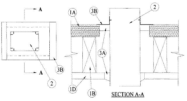
1.Floor-Ceiling Assembly — The fire-rated solid or trussed lumber joist floor-ceiling assembly shall be constructed of the materials and in the manner specified in individual L500 Series Floor-Ceiling Designs in the UL Fire Resistance Directory. The general construction details of the floor-ceiling assembly are summarized below:
A.Flooring System — Lumber or plywood subfloor with finish floor of lumber, plywood or Floor Topping Mixture* as specified in the individual Floor-Ceiling Design. Max area of floor opening is 96 sq in. (619 cm2) with max dimensions of 12 in. (305 mm).B.Wood Joists — Nom 2 by 10 in. (51 by 254 mm) lumber joists spaced 16 in. (406 mm) OC with nom 1 by 3 in. (25 by 76 mm) lumber bridging and with ends firestopped. As an alternate to lumber joists, nom 10 in. (254 mm) deep (or deeper) lumber, steel or combination lumber and steel joists, trusses or Structural Wood Members* with bridging as required with ends firestopped.C.Furring Channels — (Not Shown) — Resilient galv steel furring installed perpendicular to wood joists (Item 1B) between wallboard (Item 1D) and wood joists or furring channels as required in the individual Floor-Ceiling Design.D.Gypsum Board* — Nom 4 ft (1.2 m) wide by 5/8 in. (16 mm) thick as specified in the individual Floor-Ceiling Design. Gypsum board secured to wood joists or furring channels as specified in the individual Floor-Ceiling Design. Max area of ceiling opening is 96 sq in. (619 cm2) with max dimensions of 12 in. (305 mm).
2.Steel Duct — Nom 6 by 10 in. (152 by 254 mm) (or smaller) No. 24 gauge (or heavier) steel duct. One steel duct to be installed either concentrically or eccentrically within the firestop system. An annular space of min 3/8 in. (10 mm) to a max 1-5/8 in. (41 mm) is required within the firestop system. Steel duct to be rigidly supported on both sides of floor-ceiling assembly.
3.Firestop System — The firestop system shall consist of the following:
A.Fill, Void or Cavity Material* — Sealant — Min 3/4 in. (19 mm) thickness of fill material applied within annulus on top surface of floor. Min 5/8 in. (16 mm) thickness of fill material applied within annulus on bottom surface of ceiling. Additional fill material to be installed such that a min 1/4 in. (6 mm) thick crown is formed around the steel duct on bottom surface of ceiling.
RECTORSEAL — FlameSafe FS1900, FS1901, FS1905, FS1929, Metacaulk 1000, Metacaulk 350i, Biostop 350i or Biostop 500+B.Steel Retaining Angles — Min No. 16 gauge galv steel angles sized to lap steel duct a min of 2 in. (51 mm) and lap floor surfaces a min 1 in. (25 mm). Angles attached to steel duct on top surface of floor with min No. 8 by 1/2 in. (13 mm), long steel sheet metal screws spaced a max of 1 in. (25 mm) from each end of steel duct and spaced a max 6 in. (152 mm) OC.