F-C-7004
February 6, 2014
February 6, 2014
| ANSI/UL1479 (ASTM E814) | CAN/ULC S115 |
|---|---|
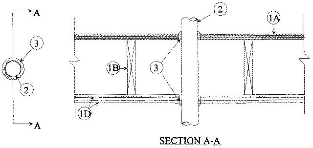
1.Floor Ceiling Assembly — The 1 hr fire-rated solid or trussed lumber joist floor-ceiling assembly shall be constructed of the materials and in the manner specified in the individual L500 Series Floor-Ceiling Designs in the UL Fire Resistance Directory. The 2 hr fire-rated wood joist floor-ceiling assembly shall be constructed of the materials and in the manner specified in Design No. L505, L511 or L536 in the UL Fire Resistance Directory, as summarized below:
A.Flooring System — Lumber or plywood subfloor with finish floor of lumber, plywood or Floor Topping Mixture* as specified in the individual Floor-Ceiling Design. Max diam of floor opening is 4-1/2 in. (114 mm).B.Wood Joists — For 1 hr fire-rated floor-ceiling assemblies nom 10 in. (254 mm) deep (or deeper) lumber, steel or combination lumber and steel joists, trusses or Structural Wood Member* with bridging as required and with ends firestopped. For 2 hr fire-rated floor-ceiling assemblies, nom 2 by 10 in. (51 by 254 mm) lumber joists spaced 16 in. (406 mm) OC with nom 1 by 3 in. (25 by 76 mm) lumber bridging and with ends firestopped.C.Furring Channels — (Not Shown) — For 2 hr fire-rated assemblies, resilient galv steel furring installed perpendicular to wood joists between first and second layers of gypsum (Item 1D) and spaced max 24 in. (610 mm) OC. In 1 hr fire-rated assemblies, resilient galv steel furring installed perpendicular to wood joists between gypsum board and wood joists where specified in the individual Floor-Ceiling Design. Furring channels spaced max 24 in. (610 mm) OC.D.Gypsum Board* — Nom 4 ft. (1.2 m) wide by 5/8 in. (16 mm) thick as specified in the individual Floor-Ceiling Design. First layer of wallboard nailed to wood joists. Second layer of gypsum screw-attached to furring channels (2 hr fire-rated assembly). Max diam of ceiling opening is 4-1/2 in. (114 mm).The Ratings of the firestop system are dependent upon the hourly rating of the assembly in which the firestop system is installed as shown in the table below:
Rating of Assembly, Hr F and FH Ratings, Hr T, FT and FTH Ratings, Hr 2 2 1-1/2 1 1 3/4
1.1.Chase Wall — (Optional, not shown) The through penetrant (Item 2) may be routed through the 1 or 2 hr fire-rated single, double or staggered wood stud/gypsum board chase wall having a fire rating consistent with that of the floor-ceiling assembly. The chase wall shall be constructed of the materials and in the manner specified in the individual U300 Series Wall and Partition Designs in the UL Fire Resistance Directory and shall include the following construction features:
A.Studs — Nom 2 by 6 in. (51 by 152 mm) or double nom 2 by 4 in. (51 by 102 mm) lumber studs.B.Sole Plate — Nom 2 by 6 in.(51 by 152 mm) or parallel 2 by 4 in. (51 by 102 mm) lumber plates, tightly butted. Max diam of opening is 4-1/2 in. (114 mm).C.Top Plate — The double top plate shall consist of two nom 2 by 6 in. (51 by 152 mm) or two sets of parallel 2 by 4 in. (51 by 102 mm) lumber plates, tightly butted. Max diam of opening is 4-1/2 in. (114 mm).D.Gypsum Board* — Thickness, type, number of layers and fasteners shall be as specified in individual Wall and Partition Design.
2.Through Penetrant — Nom 4 in. (102 mm) diam (or smaller) No. 28 MSG (or heavier) steel duct. One steel duct to be centered within the firestop system. A nom 1/4 in. (6 mm) annular space is required within the firestop system. Steel duct to be rigidly supported on both sides of floor-ceiling assembly.
3.Fill, Void or Cavity Material* — Sealant — Min 3/4 in. (19 mm) thickness of fill material applied within annulus on top surface of floor. Min 5/8 in. (16 mm) thickness of fill material applied within annulus on bottom surface of ceiling or lower top plate of chase wall assembly. Additional fill material to be installed such that a min 1/4 in. (6 mm) crown is formed around the through penetrant on top surface of floor, and bottom surface of ceiling or lower top plate of chase wall assembly.
RECTORSEAL — FlameSafe FS1900, FS1901, FS1905, FS1929, Metacaulk 1000, Metacaulk 350i, Biostop 350i or Biostop 500+