July 15, 2014
| ANSI/UL1479 (ASTM E814) | CAN/ULC S115 |
|---|---|
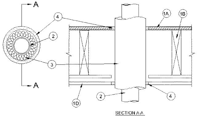
1.Floor-Ceiling Assembly — The 1 hr fire-rated solid or trussed lumber joist floor-ceiling assembly shall be constructed of the materials and in the manner specified in the individual L500 Series Floor-Ceiling Designs in the UL Fire Resistance Directory. The 2 hr fire-rated wood joist floor-ceiling assembly shall be constructed of the materials and in the manner specified in Design No. L505, L511 or L536 in the UL Fire Resistance Directory. The general construction features of the floor-ceiling assembly are summarized below:
A.Flooring System — Lumber or plywood subfloor with finish floor of lumber, plywood or Floor Topping Mixture* as specified in the individual Floor-Ceiling Design. Max diam of floor opening is 6 in. (152 mm).B.Wood Joists* — For 1 hr fire-rated floor-ceiling assemblies, nom 10 in. (254 mm) deep (or deeper) lumber, steel or combination lumber and steel joists, trusses or Structural Wood Members* with bridging as required and with ends firestopped. For 2 hr fire-rated floor-ceiling assemblies, nom 2 by 10 in. (51 by 254 mm) lumber joists spaced 16 in. (406 mm) OC with nom 1 by 3 in. (25 by 76 mm) lumber bridging and with ends firestopped.C.Furring Channels — (Not Shown) - In 2 hr fire-rated assemblies, resilient galv steel furring installed perpendicular to wood joists between first and second layers of gypsum board (Item 1D). Furring channels spaced max 24 in. (610 mm) OC. In 1 hr fire-rated assemblies, resilient galv steel furring installed perpendicular to wood joists between gypsum board and wood joists as specified in the individual Floor-Ceiling Design. Furring channels spaced max 24 in. (610 mm) OC.D.Gypsum Board* — Nom 4 ft (1.2 m) wide by 5/8 in. (16 mm) thick as specified in the individual Floor-Ceiling Design. First layer of gypsum board nailed to wood joists. Second layer of gypsum board (2 hr fire-rated assembly) screw-attached to furring channels. Max diam of ceiling opening is 6 in. (152 mm).The F and T Ratings of the firestop system are dependent upon the hourly rating of the assembly in which the firestop system is installed as shown in the table below:
Rating of Assembly, Hr F Rating, Hr T Rating, Hr 2 2 1-1/2 1 1 1
1.1.Chase Wall — (Not Shown, Optional)- The through penetrants (Item 2) may be routed through a 1 or 2 hr fire-rated single, double or staggered wood stud/gypsum board chase wall having a fire rating consistent with that of the floor-ceiling assembly. The chase wall shall be constructed of the materials and in the manner specified in the individual U300 Series Wall and Partition Designs in the UL Fire Resistance Directory and shall include the following construction features:
A.Studs — Nom 2 by 8 in. (51 by 203 mm) lumber or double nom 2 by 4 in. (51 by 102 mm) lumber studs.B.Sole Plate — Nom 2 by 8 in. (51 by 203 mm) lumber or parallel 2 by 4 in. (51 by 102 mm) lumber plates, tightly butted. Max diam of opening is 6 in. (152 mm).C.Top Plate — The double top plate shall consist of two nom 2 by 8 in. (51 by 203 mm) lumber plates or two sets of nom 2 by 4 in. (51 by 102 mm) lumber plates, tightly butted. Max diam of opening is 6 in. (152 mm).D.Gypsum Board* — Thickness, type, number of layers and fasteners shall be as specified in individual Wall and Partition Design.
2.Through Penetrants — One metallic tube or pipe to be installed within the firestop system. Tube or pipe to be rigidly supported on both sides of floor-ceiling assembly. The following types and sizes of metallic tubes or pipes may be used:
A.Copper Tubing — Nom 3 in. (76 mm) diam (or smaller) Type L (or heavier) copper tubing.B.Copper Pipe — Nom 3 in. (76 mm) diam (or smaller) Regular (or heavier) copper pipe.C.Steel Pipe — Nom 3 in. (76 mm) diam (or smaller) Schedule 10 (or heavier) steel pipe.
3.Pipe Coverings — One of the following types of pipe coverings shall be used:
A.Pipe and Equipment Covering Materials* — Nom 1 in. (25 mm) thick hollow cylindrical heavy density (min 3.5 pcf) glass fiber units jacketed on the outside with an all service jacket. Longitudinal joints sealed with metal fasteners or factory-applied self-sealing lap tape. Transverse joints secured with metal fasteners or with butt tape supplied with the product. The annular space between the insulated penetrating item and the periphery of the opening shall be a min of 3/8 in. (10 mm) to a max of 5/8 in. (16 mm).See Pipe and Equipment Covering-Materials - (BRGU) category in the Building Materials Directory for names of manufacturers. Any pipe covering material meeting the above specifications and bearing the UL Classification Marking with a Flame Spread Index of 25 or less and a Smoke Developed Index of 50 or less may be used.
B.Tube Insulation — Plastics+ — Nom 3/4 in. (19 mm) thick acrylonitrile butadiene/polyvinyl chloride (AB/PVC) flexible foam furnished in the form of tubing. The annular space between the insulated through penetrant and the periphery of the opening shall be a min of 3/8 in. ( 10 mm) to a max of 5/8 in. (16 mm).See Plastics+ (QMFZ2) category in the Plastics Component Directory for names of manufacturers. Any Recognized Component tube insulation material meeting the above specifications and having a UL94 Flammability Classification of 94-5VA may be used.
C.Pipe Covering Materials* — Nom 1 in. (25 mm) thick mineral fiber pipe insulation sized to the outside diam of pipe or tube. Pipe insulation secured with min 8 AWG steel wire space max 12 in. (305 mm) OC. The annular space between the insulated through penetrant and the periphery of the opening shall be a min of 3/8 in. (10 mm) to a max 5/8 in. (16 mm).
INDUSTRIAL INSULATION GROUP L L C — High Temperature Pipe Insulation 1200, High Temperature Pipe Insulation BWT or High Temperature Pipe Insulation Thermaloc.D.Sheathing Material* — Used in conjunction with Item 3C. Foil-scrim-kraft or all service jacket material shall be wrapped around the outer circumference of the pipe insulation (Item 3C) with the kraft side exposed. Longitudinal joints and transverse joints sealed with metal fasteners or butt tape.See Sheathing Materials (BVDV) category in the Building Materials Directory for names of manufacturers. Any sheathing material meeting the above specifications and bearing the UL Classification Marking with a Flame Spread Index of 25 or less and a Smoke Developed Index of 50 or less may be used.
4.Fill, Void or Cavity Materials* - Sealant — Min 3/4 in. (19 mm) thickness of sealant applied within annular space, flush with top surface of floor. Min 5/8 in. (16 mm) thickness of sealant applied within the annular space, flush with bottom surface of gypsum board ceiling or lower top plate of chase wall assembly.
RECTORSEAL — FS 900+ Sealant, Metacaulk MC 150+, Biostop BF 150+
+Bearing the UL Recognized Component Mark