F-C-3068
April 4, 2002
April 4, 2002
F Rating — 1 Hr
T Rating — 1 Hr
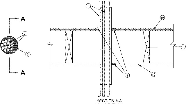
1.Floor-Ceiling Assembly — The 1 hr fire-rated wood joint floor ceiling assembly shall be constructed of the materials and in the manner specified in the individual L500 Designs in the UL Fire Resistance Directory, as summarized below:
A.Flooring System — Lumber or plywood subfloor with finish floor of lumber, plywood or Floor Topping Mixture* as specified in the individual Floor-Ceiling Design. Max diam of floor opening is 4-1/2 in.B.Wood Joists — Nom 10 in. deep (or deeper) lumber, steel or combination lumber and steel joists, trusses or Structural Wood Members* with bridging as required and with ends firestopped.C.Gypsum Board* — Nom 5/8 in. thick as specified in the individual Floor-Ceiling Design. Diam of opening to be max 1 in. larger than diam of bundled penetrants.
1A.Chase Wall — (Optional, Not Shown) — The through penetrants (Item 2) may be routed through a 1 hr fire-rated single, double or staggered wood stud/gypsum board chase wall. Depth of chase wall stud cavity to be min 1/2 in. greater than diameter of opening cut in sole and top plates to accommodate the through penetrant (Item 2). The chase wall shall be constructed of the materials and in the manner specified in the individual U300 Series Wall and Partition Designs in the UL Fire Resistance Directory and shall include the following construction features:
A.Studs — Nom 2 by 4 in., 2 by 6 in. or double nom 2 by 4 in. lumber studs.B.Sole Plate — Nom 2 by 4 in., 2 by 6 in. or parallel 2 by 4 in. lumber plates, tightly butted. Max diam of opening is to be 1 in. larger than diam of pipe.C.Top Plate — The double top plate shall consist of two nom 2 by 4 in., two nom 2 by 6 in. or two sets of parallel 2 by 4 in. lumber plates, tightly butted. Max diam of opening is to be 1 in. larger than diam of pipe.D.Gypsum Board* — Thickness, type, number of layers and fasteners shall be as specified in the individual Wall and Partition Design.
2.Cables — Max 3 in. diam bundle of cables to be installed within the opening. At the plywood subfloor, bundled cables to be installed either concentrically or eccentrically within the opening with an annular space of min 0 in. (point contact) to max 1 in. At gypsum board ceiling, bundled cables to be installed either concentrically or eccentrically within the opening. Bundled cables to be rigidly supported on both sides of the floor-ceiling assembly. The following types and sizes of copper conductor cables shall be utilized in the opening:
A.Max 750 MCM power cables; THHN or THWN jacketed. B.Max 8C, No.12 AWG multiconductor power and control cables; jacketed. C.Max 300 pair No. 24 AWG copper conductor communication cable with polyvinyl chloride insulation and jacket material. D.Max 25 pr/24 AWG telephone cable with polyethylene insulation and polyvinyl chloride jacket. E.Max 4/C No. 18 AWG (or smaller) thermostat cable with PVC insulation and jacket. F.Max 3C w/gnd, No. 12 AWG (or smaller) Romex NMC or SER w/pvc insulation and jacket. G.Max 3C w/gnd, 2/0 AWG, Type SER aluminum, polyvinyl insulation and jacket. H.Max 3C w/gnd, No. 6 AWG, Type NMC.
3.Firestop System — The firestop system shall consist of the following:
A.A. Fill,Void or Cavity Material* — Caulk — Min 3/4 in. thickness of fill material applied within the annulus, flush with the top surface of the floor sole plate. Min 5/8 in. thickness of fill material applied within the annulus, flush with bottom surface of ceiling or top plate. Min 1/2 in. diam bead of fill material applied at point contact location on the top surface of floor or sole plate and at the penetrant/ceiling or top plate interface.
RECTORSEAL — MC 150+ Caulk
+Bearing the UL Recognized Component Marking