F-C-2411
October 2, 2012
October 2, 2012
| ANSI/UL1479 (ASTM E814) | CAN/ULC S115 |
|---|---|
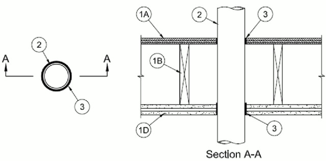
1.Floor Ceiling Assembly — The 2 hr fire rated wood joist floor-ceiling assembly shall be constructed of the materials and in the manner specified in Design Nos. L505, L511 or L536 in the UL Fire Resistance Directory. The general construction features of the floor-ceiling assembly are summarized below:
A.Flooring System — Lumber or plywood subfloor with finish floor of lumber, plywood or Floor Topping Mixture* as specified in the individual Floor-Ceiling Design. Max diam of floor opening is 4 in. (102 mm).B.Wood Joists* — For 2 hr fire rated floor-ceiling assemblies, nom 2 by 10 in. (51 by 254 mm) lumber joists spaced 16 in. (406 mm) OC with nom 1 by 3 in. (25 by 76 mm) lumber bridging and with ends firestopped.C.Furring Channels — (Not Shown) — In 2 hr fire rated assemblies, resilient galv steel furring installed perpendicular to wood joists between first and second layers of gypsum board (Item 1D). Furring channels spaced max 24 in. OC. In 1 hr fire rated assemblies, resilient galv steel furring installed perpendicular to wood joists between gypsum board and wood joists as specified in the individual Floor-Ceiling Design. Furring channels spaced max 24 in. OC.D.Gypsum Board* — Nom 4 ft wide by 5/8 in. thick as specified in the individual Floor-Ceiling Design. First layer of gypsum board secured to wood joists or furring channels as specified in the individual Floor-Ceiling Design. Second layer of gypsum board screw-attached to furring channels as specified in the individual Floor-Ceiling Design. Max diam of ceiling opening is 4 in. (102 mm).
2.Through Penetrants — One nonmetallic pipe or conduit to be installed approximately midway between wood joists and centered within the firestop system. Diam of openings hole-sawed through flooring system and through gypsum board ceiling to be nom 1/2 in. (13 mm) to 1-1/8 in. (29 mm) larger than the outside diam of through-penetrant. Pipe or conduit to be rigidly supported on both sides of the floor-ceiling assembly. The following types and sizes of nonmetallic pipes or conduits may be used:
A.Polyvinyl Chloride (PVC) Pipe — Nom 2 in. (51 mm) diam (or smaller) Schedule 40 solid or cellular core PVC pipe for use in closed (process or supply) piping systems.B.Chlorinated Polyvinyl Chloride (CPVC) Pipe — Nom 2 in. (51 mm) diam (or smaller) SDR13.5 CPVC pipe for use in closed (process or supply) piping systems.C.Electrical Nonmetallic Tubing (ENT+) — Nom 2 in. (51 mm) diam (or smaller) corrugated-wall electrical nonmetallic tubing (ENT) constructed of polyvinyl chloride (PVC) and installed in accordance with the National Electrical Code (NFPA No. 70).See Electrical Nonmetallic Tubing (FKHU) category in the Electrical Construction Materials Directory for names of manufacturers.
D.Rigid Nonmetallic Conduit (RNC)+ — Nom 2 in. (51 mm) diam (or smaller) Schedule 40 PVC conduit installed in accordance with Article 347 of the National Electrical Code (NFPA No. 70).
3.Fill, Void or Cavity Material* — Sealant — Min 3/4 in. (19 mm) thickness of fill material applied within annulus on top surface of floor. Min 1-1/4 in. (32 mm) thickness of fill material applied within annulus on bottom surface of ceiling.
RECTORSEAL — Metacaulk 1000, Biostop 500+, FlameSafe FS1900