F-C-2221
December 28, 2023
December 28, 2023
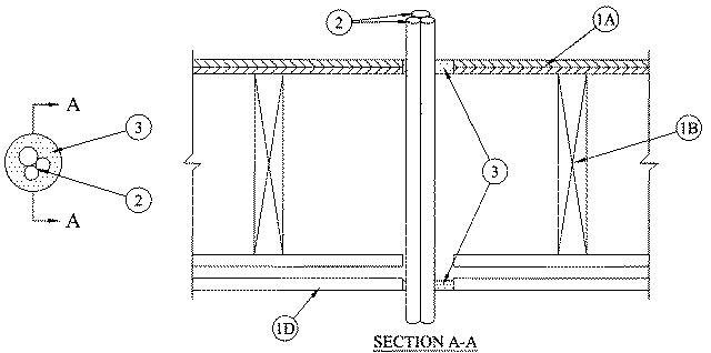
1.Floor-Ceiling Assembly — The 1 hr fire-rated solid or trussed lumber joist floor-ceiling assembly shall be constructed of the materials and in the manner specified in the individual L500 Series Floor-Ceiling Designs in the UL Fire Resistance Directory. The 2 hr fire-rated wood joist floor-ceiling assembly shall be constructed of the materials and in the manner specified in Design Nos. L505, L511 or L536 in the UL Fire Resistance Directory. The general construction features of the floor-ceiling assembly are summarized below:A.Flooring System — Lumber or plywood subfloor with finish floor of lumber, plywood or Floor Topping Mixture* as specified in the individual Floor-Ceiling Design. Max diam of floor opening is 3 in. (76 mm).B.Wood Joists* — For 1 hr fire-rated floor-ceiling assemblies nom 10 in. (254 mm) deep (or deeper) lumber, steel or combination lumber and steel joists, trusses or Structural Wood Members* with bridging as required and with ends firestopped. For 2 hr fire-rated floor-ceiling assemblies, nom 2 by 10 in. (51 by 254 mm) lumber joists spaced 16 in. (406 mm) OC with nom 1 by 3 in. (25 by 76 mm) lumber bridging and with ends firestopped.C.Furring Channels — (Not Shown) — In 2 hr fire-rated assemblies, resilient galv steel furring installed perpendicular to wood joists between first and second layers of gypsum board (Item 1D). Furring channels spaced max 24 in. (610 mm) OC. In 1 hr fire-rated assemblies, resilient galv steel furring installed perpendicular to wood joists between gypsum board and wood joists as specified in the individual Floor-Ceiling Design. Furring channels spaced max 24 in. (610 mm) OC.D.Gypsum Board* — Nom 4 ft (1.2 m) wide by 5/8 in. (16 mm) thick as specified in the individual Floor-Ceiling Design. First layer of gypsum board secured to wood joists or furring channels as specified in the individual Floor-Ceiling Design. Second layer of gypsum board (2 hr fire-rated assembly) screw-attached to furring channels as specified in the individual Floor-Ceiling Design. Max diam of ceiling opening is 3 in. (76 mm).
1.1Chase Wall — (Not Shown, Optional) — The through penetrants (Item 2) may be routed through a 1 or 2 hr fire-rated single, double or staggered wood stud/gypsum board chase wall having a fire rating consistent with that of the floor-ceiling assembly. The chase wall shall be constructed of the materials and in the manner specified in the individual U300 Series Wall and Partition Designs in the UL Fire Resistance Directory and shall include the following construction features:A.Studs — Nom 2 by 6 in. (51 by 152 mm) lumber or double nom 2 by 4 in. (51 by 102 mm) lumber studs.B.Sole Plate — Nom 2 by 6 in. (51 by 152 mm) lumber or parallel 2 by 4 in. (51 by 102 mm) lumber plates, tightly butted. Max diam of opening is 3 in. (76 mm).C.Top Plate — The double top plate shall consist of two nom 2 by 6 in. (51 by 152 mm) lumber plates or two sets of nom 2 by 4 in. (51 by 102 mm) lumber plates tightly butted. Max diam of opening is 3 in. (76 mm).D.Gypsum Board* — Thickness, type, number or layers and fasteners shall be as specified in individual Wall and Partition Designs.
2Through Penetrant — The following types of through penetrants shall be used:A.Cross-Linked Polyethylene Tubing — A max of three SDR 9 (or heavier) cross-linked polyethylene (PEX) tubing for use in closed (process or supply) piping systems. Of the three tubes, a max of one shall have a nom diam greater than 3/4 in. (19 mm). The max diam of one tube is 1 in. (25 mm). The annular space between the tubing and the periphery of the opening shall be a min 3/16 in. (4.8 mm) and a max of 1 in. (25 mm). The space between the tubing shall be a min 0 in. (point contact) to a max 1/4 in. (6 mm). Tubing to be rigidly supported on both sides of the floor-ceiling assembly.B.Aluminum Cross-Linked Polyethylene Tubing — A max of three nominal 3/4 in. (19 mm) diameter SDR 9 (or heavier) aluminum cross-linked polyethylene ( AL PEX) tubing for use in closed (process or supply) piping systems. The annular space between the tubing and the periphery of the opening shall be a min 1/8 in. (3.2 mm) and a max of 1 in. (25 mm). The space between the tubing shall be a min 0 in. (point contact) to a max 1/4 in. (6 mm). Tubing to be rigidly supported on both sides of the floor-ceiling assembly.
3.Fill, Void or Cavity Material* — Sealant — Min 3/4 in. (19 mm) thickness of fill material applied flush with annulus on top surface of floor or sole plate. Min 1/2 in. (13 mm) thickness of fill material applied flush with annulus on bottom surface of ceiling or on bottom surface of lower top plate of chase wall assembly. Additional fill material forced within the group of tubing to max extent possible on the top surface of floor or sole plate and bottom surface of ceiling or on bottom surface of lower plate of chase wall assembly.The hourly F and T Ratings of the firestop system are dependent upon the hourly rating of the floor-ceiling assembly in which it is installed, type of through penetrant and type of fill material as shown in the table below:
Rating of
Assembly,
HrType of
Through
PenetrantType of
Fill
MaterialF
Rating,
HrT
Rating,
Hr1 PEX FS 900+, Metacaulk 150+
1 1 1 AL PEX FS 900+, Metacaulk 150+
1 1 2 AL PEX FS 900+, Metacaulk 150+
2 2 1 PEX FS 1900, Metacaulk 1000, Metacaulk 350i, Biostop 350i or Biostop 500+ 1 1 2 PEX FS 1900, Metacaulk 1000, Metacaulk 350i, Biostop 350i or Biostop 500+ 2 2
RECTORSEAL — FlameSafe FS1900, FS 900+, Metacaulk 1000, Metacaulk 350i, Metacaulk 150+, Biostop 350i or Biostop 500+
Preparing PDF…