F-C-2042
May 4, 2016
May 4, 2016
| ANSI/UL1479 (ASTM E814) | CAN/ULC S115 |
|---|---|
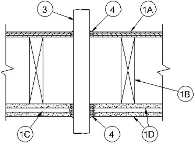
1.Floor Ceiling Assembly — The 1 hr fire-rated solid or trussed lumber joist floor-ceiling assembly shall be constructed of the materials and in the manner specified in the individual L500 Series Floor-Ceiling Designs in the UL Fire Resistance Directory. The 2 hr fire-rated wood joist floor-ceiling assembly shall be constructed of the materials and in the manner specified in Design No. L505, L511 or L536 in the UL Fire Resistance Directory. The general construction features of the floor-ceiling assembly are summarized below:
A.Flooring System — Lumber or plywood subfloor with finish floor of lumber, plywood or Floor Topping Mixture* as specified in the individual Floor-Ceiling Design. Diam of floor opening to be 1 in. to 1-5/8 in. (25 to 41 mm) larger than outside diam of through penetrant. Max diam of floor opening is 4 in. (102 mm).B.Wood Joists — For 1 hr fire-rated floor-ceiling assemblies, nom 10 in. deep (or deeper) lumber, steel or combination lumber and steel joists, trusses or Structural Wood Members* with bridging as required and with ends firestopped. For 2 hr fire-rated floor-ceiling assemblies, nom 2 by 10 in. (51 by 254 mm) lumber joists spaced 16 in. (406 mm) OC with nom 1 by 3 in. (25 by 76 mm) lumber bridging and with ends firestopped.C.Furring Channels — In 2 hr fire-rated assemblies, resilient galv steel furring installed perpendicular to wood joists between first and second layers of gypsum board (Item 1D). Furring channels spaced max 24 in. (610 mm) OC. In 1 hr fire-rated assemblies, resilient galv steel furring installed perpendicular to wood joists between gypsum board and wood joists as specified in the individual Floor-Ceiling Design. Furring channels spaced max 24 in. (610 mm) OC.D.Gypsum Board* — Nom 4 ft (1.2 m) wide by 5/8 in. (16 mm) thick as specified in the individual Floor-Ceiling Design. First layer of gypsum board nailed to wood joists. Second layer of gypsum board screw-attached to furring channels. Diam of ceiling opening to be 1 in. to 1-5/8 in. (25 to 41 mm) larger than outside diam of through penetrant. Max diam of ceiling opening is 4 in. (102 mm).
2.Chase Wall — (Not Shown, Optional) — The through penetrants (Item 3) may be routed through a 1 or 2 hr fire-rated single, double or staggered wood stud/gypsum board chase wall having a fire rating consistent with that of the floor-ceiling assembly. The chase wall shall be constructed of the materials and in the manner specified in the individual U300 Series Wall and Partition Designs in the UL Fire Resistance Directory and shall include the following construction features:
A.Studs — Nom 2 by 6 in. (51 by 152 mm) lumber or double nom 2 by 4 in. (51 by 102 mm) lumber studs.B.Sole Plate — Nom 2 by 6 in. (51 by 152 mm) lumber or parallel 2 by 4 in. (51 by 102 mm) lumber plates, tightly butted. Diam of opening in sole plate to be 1 in. to 1-5/8 in. (25 to 41 mm) larger than outside diam of through penetrant. Max diam of opening is 4 in. (102 mm).C.Top Plate — The double top plate shall consist of two nom 2 by 6 in. (51 by 152 mm) lumber plates or two sets of nom 2 by 4 in. (51 by 102 mm) lumber plates tightly butted. Diam of opening in top plate to be 1 in. to 1-5/8 in. (25 to 41 mm) larger than outside diam of through penetrant. Max diam of opening is 4 in. (102 mm).D.Gypsum Board* — Thickness, type, number or layers and fasteners shall be as specified in individual Wall and Partition Designs.
3.Through Penetrants — One nonmetallic pipe or conduit to be installed concentrically or eccentrically within the firestop system. Annular space between pipe or conduit and periphery of opening is dependent upon the hourly fire rating of the floor-ceiling assembly, and type of fill material in which it is installed as shown in Item 4. Pipe or conduit to be rigidly supported on both sides of the floor-ceiling assembly. The following types and sizes of nonmetallic pipes or conduits may be used:
A.Polyvinyl Chloride (PVC) Pipe — Nom 2 in. (51 mm) diam (or smaller) Schedule 40 solid or cellular core PVC pipe for use in closed (process or supply) or vented (drain, waste or vent) piping systems.B.Rigid Nonmetallic Conduit+ — Nom 2 in. (51 mm) diam (or smaller) Schedule 40 PVC conduit installed in accordance with the National Electrical Code (NFPA No. 70).C.Chlorinated Polyvinyl Chloride (CPVC) Pipe — Nom 2 in. (51 mm) diam (or smaller) SDR 13.5 CPVC pipe for use in closed (process or supply) piping systems.D.Electrical Nonmetallic Tubing (ENT+) — Nom 1 in. (25 mm) diam (or smaller) corrugated-wall electrical nonmetallic tubing (ENT) constructed of polyvinyl chloride (PVC) and installed in accordance with the National Electrical Code (NFPA No. 70).See Electrical Nonmetallic Tubing (FKHU) category in the Electrical Construction Materials Directory for names of manufacturers.
4.Fill, Void or Cavity Material* — Sealant — In 2 hr fire-rated assemblies, min 3/4 in. (19 mm) thickness of sealant applied within annular space, flush with top surface of floor or chase wall sole plate. Min 1-1/4 or 5/8 in. (32 or 16 mm) thickness of sealant as indicated in the table below, applied within the annular space, flush with bottom surface of gypsum board ceiling or chase wall top plate. Additional fill material to be installed such that a min 1/4 in. (6 mm) crown is formed around the penetrating item on both sides of floor-ceiling assembly. In 1 hr fire-rated assemblies, min 3/4 in. (19 mm) thickness of sealant applied within annular space, flush with top surface of floor. Min 5/8 in. (16 mm) thickness of sealant applied within the annular space, flush with bottom surface of gypsum board ceiling . Additional fill material to be installed such that a min 1/4 in. (6 mm) crown is formed around the penetrating item on both sides of floor-ceiling assembly. The F and T Ratings of the firestop system are dependent upon the hourly fire rating of the floor-ceiling assembly, min and max annular space within the firestop system and type and thickness of fill material used within the firestop system as shown in the table below:
Rating of
Assembly, Hr
Type of
Sealant
Min, Max
Annular
Space, in.
(mm)Min
Thickness
of Sealant
Within
Ceiling, in.
(mm)
F Rating, Hr
T Rating, Hr2 FS 1900, Metacaulk 1000, Metacaulk 350i, Biostop 350i or Biostop 500+ 1/2, 1-1/8 (13, 38) 1-1/4 (32) 2 0 1 FS 1900, Metacaulk 1000, Metacaulk 350i, Biostop 350i or Biostop 500+ 1/2, 1-1/8 (13, 38) 5/8 (16) 1 0 2 FS 900+, Metacaulk 150+ and Biostop 150+ 1/2, 5/8 (13, 16) 5/8 (16) 2 0 1 FS 900+, Metacaulk 150+ and Biostop 150+ 1/2, 5/8 (13, 16) 5/8 (16) 1 1
RECTORSEAL — FlameSafe FS 1900, FS 900+, Metacaulk MC 150+, Metacaulk 1000, Metacaulk 350i, Biostop BF 150+, Biostop 350i or Biostop 500+
*Bearing the UL Classification Marking