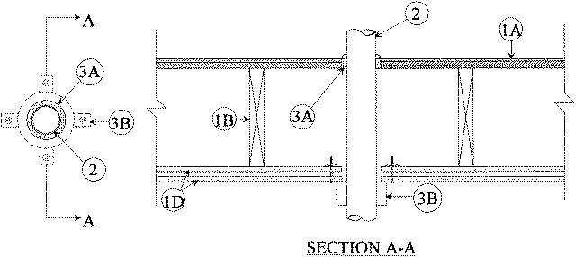
F-C-2041
July 15, 2014
July 15, 2014
| ANSI/UL1479 (ASTM E814) | CAN/ULC S115 |
|---|---|

1.Floor Ceiling Assembly — The 1 hr fire-rated solid or trussed lumber joist floor-ceiling assembly shall be constructed of the materials and in the manner specified in the individual L500 Series Floor-Ceiling Designs in the UL Fire Resistance Directory. The fire-rated wood joist floor-ceiling assembly shall be constructed of the materials and in the manner specified in Design No. L505, L511 or L536 in the UL Fire Resistance Directory. The general construction features of the floor-ceiling assembly are summarized below:
A.Flooring System — Lumber or plywood subfloor with finish floor of lumber, plywood or Floor Topping Mixture* as specified in the individual Floor-Ceiling Design. Max diam of floor opening is 5 in. (127 mm).B.Wood Joists — For 1 hr fire-rated floor-ceiling assemblies nom 10 in. (254 mm) deep (or deeper) lumber, steel or combination lumber and steel joists, trusses or Structural Wood Members* with bridging as required and with ends firestopped. For 2 hr fire-rated floor-ceiling assemblies, nom 2 by 10 in. (51 by 254 mm) lumber joists spaced 16 in. (406 mm) OC with nom 1 by 3 in. (25 by 76 mm) lumber bridging and with ends firestopped.C.Furring Channels — (Not Shown) — For 2 hr fire-rated assemblies, resilient galv steel furring installed perpendicular to wood joists between first and second layers of wallboard (Item 1D) and spaced max 24 in. (610 mm) OC. In 1 hr fire-rated assemblies, resilient galv steel furring installed perpendicular to wood joists between gypsum board and wood joists as specified in the individual Floor-Ceiling Design. Furring channels spaced max 24 in. (610 mm) OC.D.Gypsum Board* — Nom 4 ft (1219 mm) wide by 5/8 in. (16 mm) thick as specified in the individual Floor-Ceiling Design. First layer of gypsum board nailed to wood joists. Second layer of gypsum board screw-attached to furring channels (2 hr fire-rated assembly). Max diam of ceiling opening is 5 in. (127 mm).The F and T Ratings of the firestop system are equal to the hourly fire rating of the floor-ceiling assembly in which it is installed.
2.Through Penetrants — One nonmetallic pipe or conduit to be installed approximately midway between wood joists and centered within the firestop system. Diam of openings hole-sawed through flooring system and through gypsum board ceiling to be nom 1/4 in. (6 mm) larger than the outside diam of through-penetrant. Pipe or conduit to be rigidly supported on both sides of floor-ceiling assembly. The following types and sizes of nonmetallic pipes or conduits may be used:
A.Polyvinyl Chloride (PVC) Pipe — Nom 4 in. (102 mm) diam (or smaller) Schedule 40 solid core PVC pipe for use in closed (process or supply) piping systems.B.Rigid Nonmetallic Conduit+ — Nom 4 in. (102 mm) diam (or smaller) Schedule 40 PVC conduit installed in accordance with Article 347 of the National Electrical Code (NFPA No. 70).C.Chlorinated Polyvinyl Chloride (CPVC) Pipe — Nom 4 in. (102 mm) diam (or smaller) SDR 13.5 CPVC pipe for use in closed (process or supply) piping systems.
3.Firestop System — The firestop system shall consist of the following:
A.Fill, Void or Cavity Material* — Sealant — Fill material forced into annulus to fill space to max extent possible, flush with top surface of floor. Additional fill material to be installed such that a min 1/4 in. (6 mm) crown is formed around the penetrating item on top surface floor.
RECTORSEAL — FS 1900 or FS 900+ Sealant, Metacaulk MC 150+, Biostop BF 150+B.Firestop Device* — Galv steel collar lined with an intumescent material sized to fit the specific diam of the through-penetrant in accordance with the accompanying installation instructions. Device incorporate anchor tabs for securement to bottom surface of gypsum board ceiling by means of 1/8 in. (3 mm) diam by 3 in. (76 mm) long toggle bolts in conjunction with 1/4 in. (6 mm) by 1 in. (25 mm) diam steel fender washer.
RECTORSEAL — FSD Device
*Bearing the UL Classification Marking