F-C-1125
July 15, 2014
July 15, 2014
| ANSI/UL1479 (ASTM E814) | CAN/ULC S115 |
|---|---|
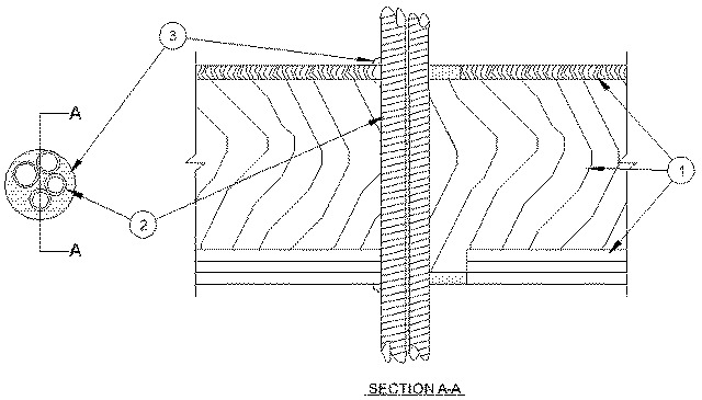
1.Floor Ceiling Assembly — The 1 hr fire-rated solid or trussed lumber joist floor-ceiling assembly shall be constructed of the materials and in the manner specified in the individual L500 Series Floor-Ceiling Designs in the UL Fire Resistance Directory. The 2 hr fire-rated wood joist floor-ceiling assembly shall be constructed of the materials and in the manner specified in Design Nos. L505, L511 or L536 in the UL Fire Resistance Directory. The general construction features of the floor-ceiling assembly are summarized below:
A.Flooring System — Lumber or plywood subfloor with finish floor of lumber, plywood or Floor Topping Mixture* as specified in the individual Floor-Ceiling Design. Max diam of floor opening is 4 in. (102 mm).B.Wood Joists* — For 1 hr fire-rated floor-ceiling assemblies nom 10 in. (254 mm) deep (or deeper) lumber, steel or combination lumber and steel joists, trusses or Structural Wood Members* with bridging as required and with ends firestopped. For 2 hr fire-rated floor-ceiling assemblies, nom 2 by 10 in. (51 by 254 mm) lumber joists spaced 16 in. (406 mm) OC with nom 1 by 3 in. (25 by 76 mm) lumber bridging and with ends firestopped.C.Furring Channels — In 2 hr fire-rated assemblies, resilient galv steel furring installed perpendicular to wood joists between first and second layers of board (Item 1D). Furring channels spaced max 24 in. (610 mm) OC. In 1 hr fire-rated assemblies, resilient galv steel furring installed perpendicular to wood joists between board and wood joists as specified in the individual Floor-Ceiling Design. Furring channels spaced max 24 in. (610 mm) OC.D.Gypsum Board* — Nom 4 ft (1.2 m) wide by 5/8 in. (16 mm) thick as specified in the individual Floor-Ceiling Design. First layer of gypsum board secured to wood joists or furring channels as specified in the individual Floor-Ceiling Design. Second layer of gypsum board (2 hr fire-rated assembly) screw-attached to furring channels as specified in the individual Floor-Ceiling Design. Max diam of ceiling opening is 4 in. (102 mm).The F Rating of the firestop system is equal to the hourly fire rating of the floor-ceiling assembly in which it is installed.
1.1Chase Wall — (Not Shown, Optional) The through penetrants (Item 2) may be routed through a 1 or 2 hr fire-rated single, double or staggered wood stud/gypsum board chase wall having a fire rating consistent with that of the floor-ceiling assembly. The chase wall shall be constructed of the materials and in the manner specified in the individual U300 Series Wall and Partition Designs in the UL Fire Resistance Directory and shall include the following construction features:
A.Studs — Nom 2 by 6 in. (51 by 152 mm) lumber or double nom 2 by 4 in. (51 by 102 mm) lumber studs.B.Sole Plate — Nom 2 by 6 in. (51 by 152 mm) lumber or parallel 2 by 4 in. (51 by 102 mm) lumber plates, tightly butted.C.Top Plate — The double top plate shall consist of two nom 2 by 6 in. (51 by 152 mm) lumber plates or two sets of nom 2 by 4 in. (51 by 102 mm) lumber plates tightly butted. Max diam of opening is 4 in. (102 mm).D.Gypsum Board* — Thickness, type, number or layers and fasteners shall be as specified in individual Wall and Partition Designs.
2.Through Penetrants — One or more nom 1-1/2 in. (38 mm) diam (or smaller) flexible steel conduit bundled together and installed within the opening. Max diam of through penetrant bundle shall be 3 in. (76 mm). The space between the through penetrants shall be a min of 0 in. (point contact) to a max of 1/4 in. (6 mm). The annular space between the through penetrants and periphery of opening shall be min 0 in. (point contact) to max 1 in. (25 mm). Through penetrants to be rigidly supported on both sides of floor-ceiling assembly assembly.See Flexible Metal Conduit (DXUZ) category in the Electrical Construction Materials Directory for names of manufacturers.
3.Fill, Void or Cavity Material* — Sealant — Min 3/4 in. (19 mm) thickness of fill material applied within the annulus, on the top surface of the floor or sole plate. Min 5/8 in. (16 mm) thickness of fill material applied within the annulus, flush with bottom surface of ceiling or bottom top plate. Additional min 1/8 in. (3.2 mm) thickness of sealant shall extend a min 1/2 in. (13 mm) beyond the periphery of the opening on the top surface of the floor or sole plate and bottom surface of the ceiling or bottom top plate. At point contact, min 3/8 in. (10 mm) diam bead of fill material applied at penetrant/floor or sole plate interface and at penetrant/ceiling or top plate interface. Additional sealant shall be forced into interstices of through penetrants to max extent possible.
RECTORSEAL — FS900+ Sealant, Metacaulk MC 150+, Biostop BF 150+