F-B-3009
August 5, 2004
August 5, 2004
F Rating — 3 Hr
T Ratings — 0, 1-3/4, 2-1/4, 2-1/2 and 2-3/4 Hr (See Items 3 and 4)
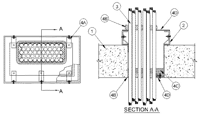
1.Floor Assembly — Min 8 in. thick reinforced normal weight (145-150 pcf) concrete. Max area of opening is 288 sq. in.with max dimension of 24 in.
2.Sheathing Channels — (Optional, See 4D) Nom 1 in. by 4 in. high by 1/4 in. thick structural steel channels with mitered ends formed into four sided enclosure with welded corners. Inside dimensions of enclosure, between flange tips, to be equal to the inside dimensions of the floor opening. Sheathing channels secured to concrete floor by means of min 1/4 in. diam by 1-1/4 in. long steel Tapcon® concrete anchors spaced max 8 in. OC around the entire perimeter of the opening.
3.Cables — Max 36 percent fill (based on the available area of the opening) of any combination of telecommunication or power cables. The cables are to be laced to the cable rack and to each other to form a tight bundle against one side of the opening with min interstices between cables. The following types of cables may be used:
A.Max 750 MCM power cables; THHN or THWN jacketed. When these cables are used, T Rating is max 1-3/4 hr. B.Max 8C, No.12 AWG multiconductor power and control cables; PVC jacketed. When these cables are used, T Rating is max 2-3/4 hr. C.Max 300 pair No. 24 AWG copper conductor communication cable with PVC insulation and jacket material. When these cables are used, T Rating is max 2-1/2 hr. D.Multiple fiber optical communication cable jacketed with PVC. When these cables are used, T Rating is max 2-1/4 hr. E.Max 25 pr/24 AWG telephone cable with polyethylene insulation and PVC jacket. When these cables are used, T Rating is max 2-3/4 hr. The T Rating of the firestop system is equal to the lowest T Rating of cable used.
4.Firestop System — The firestop system shall consist of the following items:
A.Stirrups — (Optional, See 4D) Nom 2 in. wide by 0.1 in.,12 gauge thick steel strip formed into stirrup with sufficient length to support lower cover plate (Item 4D) approx flush with bottom surface of floor. Top of stirrup angle bolted to web of sheathing channel (Item 2). Bottom of stirrup bent 90 degrees to form a 1-1/4 in. long flange for support and attachment of the bottom cover plate (Item 4D). The stirrups shall be located in each corner of the opening and spaced max 12 in. OC.B.Fill, Void or Cavity Materials* — Putty — After installation of the bottom steel cover plate (Item 4D) putty shall be packed around the perimeter of the cable bundle at its egress from the steel cover plate. The "dome" of putty shall be min 1 in. thick and extend to min height of 2 in. above the top of the bottom steel cover plate. One layer of 1/2 in. wide strip of putty positioned under top cover plate (Item 4D) around entire perimeter of through opening at its interface with surface of sheathing channel (Item 2) or surface of floor. After installation of top cover plate (Item 4D) additional putty to be "domed" around the perimeter of the cable bundle to a min thickness of 1 in. and to a height of 2 in. above the top of the top cover plate.
RECTORSEAL — Metacaulk Fire Rated PuttyC.Fill, Void or Cavity Material* — Intumescent Block — The block material cross-section is nom 1 in. square. The fill material is cut into two 8 in. long blocks and two 10 in. long blocks installed within the concrete opening cavity. For smaller openings, the length of block material may be trimmed to 80% of the length and the width of the opening size. Pieces of the material are stacked on top of the bottom cover plate (Item 4D) within the cavity between the "domed" putty around the cable bundle and the edge of the opening.
RECTORSEAL — Metacaulk Bixi StixD.Steel Cover Plate — U-shaped bottom cover plate is formed of min 0.028 in., 24 gauge galv steel cut to fit contour of the cable bundle. Bottom cover plate is attached to 1-1/4 in. flange of stirrups (Item 4A) with 1/4 in. diam by 1 in. long steel bolts with nuts and washers spaced max 8 in. OC or can be attached to floor using min 1/4 in. diam by 1-1/4 in. long steel Tapcon® concrete anchors spaced max 8 in. OC around the entire perimeter of the opening. U-shaped top cover plate is formed of min 0.100 in., 12 gauge galv steel cut to fit the contour of the cable bundle. Steel cover plate placed on top of putty strips and secured to sheathing, through putty, with steel screws spaced max 8 in. OC or can be attached to floor using min 1/4 in. diam by 1-1/4 in. long steel Tapcon® concrete anchors spaced max 8 in. OC around the entire perimeter of the opening and overlapping opening by nominal 1-1/2 in.When attached to the floor the T-Rating is 0 Hr.