June 24, 2020
| ANSI/UL1479 (ASTM E814) | CAN/ULC S115 |
|---|---|
- System tested with a pressure differential of 2.5 Pa between the exposed and the unexposed surfaces with the higher pressure on the exposed side.
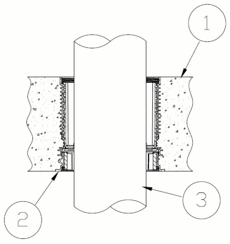
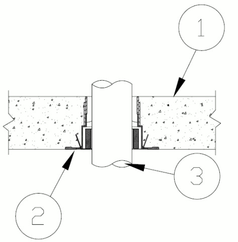
1.Floor Assembly — Min 6 in. (152 mm) thick reinforced lightweight or normal weight (100-150 pcf or 1600-2400 kg/m3) concrete measured above the base of the device.
2.Firestop Device* — Cast in place firestop device permanently embedded during concrete placement in accordance with accompanying installation instructions. The device shall be installed flush with top and bottom surfaces of floor. The devices are sized to accommodate the following nom pipe sizes:Configuration A HFP devices and optional accessories (not shown) includes sleeve extension, water module, aerator adapter and/or Water dam installed in accordance with installation instructions.
Configuration B devices, optional accessory (not shown) aerator adapter installed in accordance with the installation instructions.
The devices are sized to accommodate the following nom pipe sizes:
Nom Pipe Diam
in. (mm)Conf A
Firestop Devices for Concrete SlabConf B
Firestop Devices for Concrete Slab1/2 to 1-1/4* (13 to 32*) HFP-M1, HFP-M1B, HFP-P1, HFP-P1B WD-PL-0100, OPS-PL-0100, OPS-MT-0100 1-1/4 to 2 (32 to 51) HFP-M2, HFP-M2B, HFP-P2, HFP-P2B WD-PL-0200, OPS-PL-0200, OPS-MT-0200 2 to 3 (51 to 76) HFP-M3, HFP-M3B, HFP-P3, HFP-P3B WD-PL-0300, OPS-PL-0300, OPS-MT-0300 3 to 4 (76 to 102) HFP-M4, HFP-M4B, HFP-P4, HFP-P4B WD-PL-0400, OPS-PL-0400, OPS-MT-0400 4 to 5 (102 to 127) HFP-M5, HFP-M5B, HFP-P5, HFP-P5B NA 5 to 6 (127 to 152) HFP-M6, HFP-M6B, HFP-P6, HFP-P6B WD-PL-0600, OPS-PL-0600, OPS-MT-0600 *Refer to W & L Rating table below
When penetrant diameters are smaller than permitted in the table above, the use of Items 4B is required and Item 5 optional
HOLDRITE —HydroFlame OPS-MT, OPS-PL, WD-PL, HFP-Mx, HFP-MxB, HFP-Px HFP-PxB
3.Through Penetrant — One metallic pipe, conduit or tubing to be installed within the firestop device. Pipe, conduit or tubing to be installed in accordance with firestop device installation instructions and rigidly supported on both sides of floor assembly. The following types of pipe, conduit or tubing may be used:
A.Steel Pipe — Nom 6 in. (152 mm) diam (or smaller) Schedule 10 (or heavier) steel pipe.B.Iron Pipe — Nom 6 in. (152 mm) diam (or smaller) cast or ductile iron pipe.C.Conduit — Nom 6 in. (152 mm) diam (or smaller) rigid steel conduit or nom 4 in. (102 mm) diam steel electrical metallic tubing.D.Copper Tubing — Nom 6 in. (152 mm) diam (or smaller) Type L (or heavier) copper tubing.E.Copper Pipe — Nom 6 in. (152 mm) diam (or smaller) Regular (or heavier) copper pipe.F.Steel Flexible Metal Conduit — Nom 4 in. (102 mm) diam (or smaller) steel flexible metal conduit.W rating does not apply.
G.Aluminum Flexible Metal Conduit — Nom 1-1/2 in. (38 mm) diam (or smaller) aluminum flexible metal conduit.W Rating does not apply.
See Flexible Metal Conduit (DXUZ) category in the Electrical Construction Materials Directory for names of manufacturers. W-Rating not applicable.
3A.Through Penetrating Product* Flexible Metal Piping — As an alternate to the flexible metal conduit (Item 3G), one nom 2 in. (51 mm) diam (or smaller) steel flexible metal piping may be installed concentrically within the firestop system. Piping to be rigidly supported on both sides of wall assembly.
OMEGA FLEX INC
GASTITE, DIV OF TITEFLEX —CSST or FlashShield CSST
WARD MFG L L C W-Rating Does not apply when Item 3F or 3G is installed.
4.Packing Material — (Optional, Not Shown) — Min 2 in. (51 mm) depth of min 4 pcf (64 kg/m3) mineral wool batt insulation tightly-packed into annular space between penetrant and device with its top surface flush with the top surface of the floor. When optional sealant (Item 5) is used, top surface of packing material to be recessed min 1/4 in. (6 mm) from top surface of floor. Config. B (Only) W Rating applies only when packing material and sealant (Item 5) is used.
4A.Packing Material — (Optional instead of 4, Not Shown) — Foam backer rod firmly packed into opening as a permanent form. Packing material to be recessed from top surface of floor as required to accommodate the required thickness of fill material.
4B.Packing Material — (Optional instead of Item 4, Not Shown) — For Configuration A only. When penetrant diameters are smaller than the device size range in the table above, Min. 3-3/4 in. depth from floor surface or to fullest extent possible to top of inner seal of min 4 pcf (64 kg/m3) mineral wool batt insulation tightly-packed into annular space between penetrant and device, flush with the top surface of the floor. When optional sealant (Item 5) is used, top surface of packing material to be recessed min 1/4 in. (6 mm) from top surface of floor.
5.Fill, Void or Cavity Material* — Sealant — (Optional, Not Shown) — Min 1/4 in. (6 mm) thickness of sealant applied within the annulus, flush with the top surface of floor. A Min 1/2 in. (13 mm) thickness of sealant applied within the annulus, flush with the top surface of floor to attain W-Rating. Conf B (Only), Sealant to lap min 1/2 in. (13 mm) onto top surface of concrete around perimeter of firestop device. As an alternate when sealant is optional 100% silicone sealant can be used.For Configuration A (ONLY), the W Rating and L Ratings apply
Device size Penetrant with (IPS) Diam in. (mm) Penetrant with (CTS) Diam in. (mm) W RATING L Rating HFP-x1, HFP-x1B 1/2 to 1 (13 to 25) 1/2 to 1-1/4 (13 to 32) YES YES HFP-x2, HFP-x2B 1-1/4 to 2 (32 to 51) 1-1/2 to 2 (38 to 51) YES YES HFP-x2, HFP-x2B N/A 1-1/4 (32) YES, with Items 4 or 4A& 5 Above YES, with Items 4 or 4A& 5 Above HFP-x3, HFP-x3B 2 to 3 (51 to 76 2-1/2 to 3 (64 to 76) YES YES HFP-x3, HFP-x3B N/A 2 (51) YES, with Items 4 or 4A & 5 Above YES, with Items 4 or 4A & 5 Above HFP-x4, HFP-x4B 3 to 4 (76 to 102) 3-1/2 to 4 (89 to 102) YES YES HFP-x4, HFP-x4B N/A 3 (76) YES, with Items 4 or 4A & 5 Above YES, with Items 4 or 4A & 5 Above HFP-x5, HFP-x5B 4 to 5 (102 to 127) 5 (127) YES YES HFP-x5, HFP-x5B N/A 4 (102) YES, with Items 4 or 4A & 5 Above YES, with Items 4 or 4A & 5 Above HFP-x6, HFP-x6B 5 to 6 (127 to 152) 6 (152) YES YES HFP-x6, HFP-x6B N/A 5 (127) YES, with Items 4 or 4A & 5 Above YES, with Items 4 or 4A & 5 Above Note: IPS is Iron pipe diameter standard and CTS is Copper tube diameter standard/
If inner seal is torn or compromised in any way, Items 4 and Item 5 can be used to achieve W and L Ratings. When the penetrant is smaller than the device range sealant (Item 5) must be used to obtain W and L Rating
For Configuration B, W Rating and L Ratings apply only when packing material (Item 4) and sealant (Item 5) is used.
RELIANCE WORLDWIDE CORPORATION DBA HOLDRITE HYDROFLAME —HydroFlame 100, HydroFlame 200, HydroFlame 300SL, HydroFlame 300 CG
6.Pipe Tee Fitting System — (Optional, Not Shown) — For use with Iron Pipe (Item 3B) only, One nom 6 in. (152 mm) diam (or smaller) PVC TESTRITE TEE Fitting (matched to penetrant diameter). The PVC TESTRITE TEE Fitting is secured to metallic penetrant (Item 3B) with compression type pipe coupling elastomeric gasket with stainless steel jacket and stainless steel band clamps for use in vented (drain, waste or vent) iron pipe systems. Installed (Item 3B) penetrant shall extend a minimum of 6 in. (152 mm) above the surface of the floor and minimum 12 in. (302 mm) below the bottom surface of the floor assembly.