April 20, 2021
| ANSI/UL1479 (ASTM E814) | CAN/ULC S115 |
|---|---|
System tested with a pressure differential of 2.5 Pa between the exposed and the unexposed surfaces with the higher pressure on the exposed side.
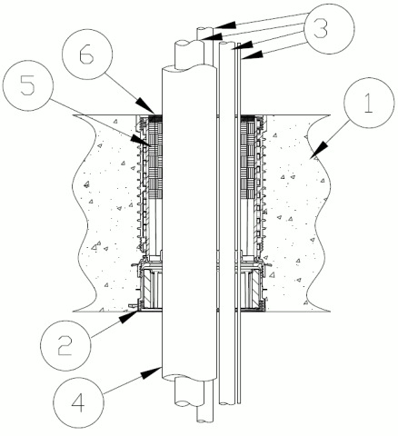
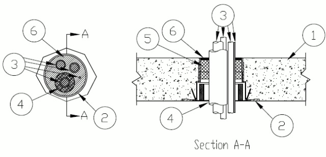
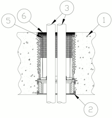
1.Floor Assembly — Min 4-1/2 in. (114 mm) thick reinforced lightweight or normal weight (100-150 pcf or 1600-2400 kg/m3) concrete.
1A.Alternate Floor Assembly — (Not Shown) — The fire rated unprotected concrete and steel deck floor assembly shall be constructed of the material and in the manner specified in the individual D900 Series designs in the UL Fire Resistance Directory and as summarized below:A.Concrete — Min 4-1/2 in. (114 mm) thick reinforced lightweight or normal weight (100-150 pcf or 1600-2400 kg/m3) concrete, as measured from the top plane of the steel floor units. When concrete thickness is min 4-1/2 in. (114 mm), the F and FH Ratings are 3 hr.B.Steel Floor and Form Units* — Composite or non-composite max 3 in. (76 mm) deep galv steel fluted units as specified in the individual Floor-Ceiling Design.
2.Firestop Device* — Cast in place firestop device permanently embedded during concrete placement or grouted in concrete assembly in accordance with accompanying installation instructions. For HFP devices in configuration A the optional accessories (not shown) includes a sleeve extension and deck adapter, installed in accordance with manufactures instructions.
Conf A Firestop Devices for Concrete Slab Conf B Firestop Devices for Concrete Slab Conf B Firestop Devices for Fluted Deck (Not Shown) Conf A Firestop Devices for Fluted Deck (Not Shown) HFP-LSP3, HFP-LSP3B, HFP-P3, HFP-P3B, HFP-H4, HFP-H4B PS-LS-0300, OPS-PL-0300, WD-PL-0400, WD Sleeve CD-LS-0300, CD-OPS-PL-0300, CD-PL-0400, CD Sleeve add HFPCD3
HOLDRITE — HydroFlame PS-LS, CD-LS HFP-LS3, OPS-PL, CD-OPS, WD-PL, CD-PL, WD, CD, HFP-LS3B, HFP-P3, HFP-P3B, HFP-H4, HFP-H4B
3.Through Penetrants — Pipes, tubing or cable to be bundled within the opening. The space between penetrants and the space between the penetrants and the inside of the firestop device (Item 2) at top of floor shall be min 1/4 in. (6 mm). Penetrants to be rigidly supported on both sides of floor assembly. The following types and sizes of penetrants may be used:A.Metallic Pipes — Max four of the following types and sizes of metallic pipe or tubing may be used:1.Copper Tubing — Nom 3/4 in. (19 mm) diam (or smaller) Type M (or heavier) copper tubing.2.Copper Pipe — Nom 3/4 in. (19 mm) diam (or smaller) Regular (or heavier) copper pipe.B.Polyvinyl Chloride (PVC) Pipe — A max of one Nom 1 in. (25 mm) diam (or smaller) Schedule 40 solid core PVC pipe for use in closed (process or supply) piping systems.B1.Polyvinyl Chloride (PVC) Pipe — As an alternate to Item B, Max of one Nom 1 in. (25 mm) diam (or smaller) solid or cellular core Schedule 40 polyvinyl chloride (PVC) pipe.
IPEX INC — System 15 pipingB2.XFR Polyvinyl Chloride (PVC) Pipe — As an alternate to Item B, Max of one Nom. 1 in. (25 mm) (or smaller) Schedule 40 IPEX XFR pipe for use in closed (process or supply) or vented (drain, waste or vent) piping systems.C.Cable — One max 8/C No. 18 AWG (or smaller) thermostat cable; XLPE or PVC insulation with XLPE or PVC jacket.D1.Cable — Max four total - Nom 3/4 in. (19 mm) diam (or smaller) aluminum or steel Metal Clad Cable (Type MC). W-Rating not applicable.D2.Cable — Alternate to item 3D1 Max four total - 3/C No. 4/0 AWG (or smaller) copper or aluminum conductor SER or MCM cables with XLPE or PVC insulation and jacket. W-Rating not applicable.E.Through Penetrating Product* — Flexible Metal Piping — As an alternate to the metal pipes (Item 3A), one nom 2 in. (51 mm) diam (or smaller) steel flexible metal piping may be installed concentrically within the firestop system. Piping to be rigidly supported on both sides of wall assembly.
OMEGA FLEX INC — Flexible metal gas piping
GASTITE, DIV OF TITEFLEX — CSST or FlashShield CSST
WARD MFG L L C — Wardflex, Wardflex Max and Wardflex II
W-Rating Not applicable when Item 3D1 or 3D2 is installed.
F1.Cross-Linked Polyethylene (PEX) Pipe (for use with HFP series devices only) — As an alternate to Item F, Max of one Nom 1 in. (25 mm) diam (or smaller) SharkBite SDR 9 PEX tubing for use in closed (process or supply) piping systems.G.Polypropylene (PP) Pipe (for use with HFP series devices only) — Max of one Nom 1 in. (25 mm) diam (or smaller) Aquatherm SDR 7.4, 11 or 17.4 PP pipe for use in closed (process or supply) piping systems.G1.Polypropylene PP-RCT Pipe (for use with HFP series devices only) — As an alternate to Item G, Max of one Nom 1 in. (25 mm) diam (or smaller) Nupi - Niron SDR 7.4, 11 or 17.4 PP pipe for use in closed (process or supply) piping systems.
2.Firestop Device* — Cast in place firestop device permanently embedded during concrete placement or grouted in concrete assembly in accordance with accompanying installation instructions. For HFP devices in configuration C the optional accessories (not shown) includes a sleeve extension and deck adapter, installed in accordance with manufactures instructions.
Conf C Firestop Devices for Concrete Slab Conf C Firestop Devices for Fluted Deck (Not Shown) HFP-P3, HFP-P3B, HFP-LS3, HFP-LS3B, HFP-H4, HFP-H4B add HFPCD3
HOLDRITE — HydroFlame HFP-P3, HFP-P3B, HFP-LS3, HFP-LS3B, HFP-H4, HFP-H4B
3.Through Penetrants (For use with HFP3, and HFP3B devices only) — Max of two of the same or different pipes, tubing to be bundled within the opening. The space between penetrants and the space between the penetrants and the inside of the firestop device (Item 2) at top of floor shall be min 1/4 in. (6 mm). Penetrants to be rigidly supported on both sides of floor assembly. The following types and sizes of penetrants may be used:A.Cross-Linked Polyethylene (PEX) Tubing — A max of two nom 1 in. (25 mm) diam (or smaller) SDR 9 PEX tubing for use in closed (process or supply) piping systems.B.Polyvinyl Chloride (PVC) Pipe — A max of two nom 1 in. (25 mm) diam (or smaller) Schedule 40 solid core PVC pipe, for use in closed (process or supply) piping systems.B1.Polyvinyl Chloride (PVC) Pipe — As an alternate to Item B, Max of two Nom 1 in. (25.4 mm) diam (or smaller) solid or cellular core Schedule 40 polyvinyl chloride (PVC) pipe.
IPEX INC — System 15 pipingB2.XFR Polyvinyl Chloride (PVC) Pipe — As an alternate to Item B, Max of two Nom. 1 in. (25 mm) (or smaller) Schedule 40 IPEX XFR pipe for use in closed (process or supply) or vented (drain, waste or vent) piping systems.C.Rigid Nonmetallic Conduit+ — Max of two Nom 1 in. (25 mm) diam (or smaller) Schedule 40 PVC conduit installed in accordance with the National Electrical Code (NFPA No. 70).D.Chlorinated Polyvinyl Chloride (CPVC) Pipe — A max of two nom 1 in. (25 mm) diam (or smaller) SDR13.5 (or heavier) or Sch 40 CPVC pipe for use in closed (process or supply) piping systems.D1.Chlorinated Polyvinyl Chloride (CPVC) Pipe — As an alternate to Item D, max of two Nom 1 in. (25 mm) diam (or smaller) SDR 13.5 CPVC for use in closed (process or supply) piping systems.
IPEX INC — AquaRiseE.Cross-Linked Polyethylene (PEX) Tubing — Max of two Nom 1 in. (25 mm) diam (or smaller) SDR 9 PEX tubing for use in closed (process or supply) piping systems.E1.Cross-Linked Polyethylene PEX Pipe — As an alternate to Item E, Max two Nom 1 in. (25 mm) diam (or smaller) SharkBite SDR 9 PEX tubing for use in closed (process or supply) piping systems.F.Polypropylene (PP) Pipe (for use with HFP series devices only) — Max of two Nom 1 in. (25 mm) diam (or smaller) Aquatherm SDR 7.4, 11 or 17.4 PP pipe for use in closed (process or supply) piping systems.F1.Polypropylene PP-RCT Pipe — As an alternate to Item F, Max of two Nom 1 in. (25 mm) diam (or smaller) Nupi - Niron SDR 7.4, 11 or 17.4 PP pipe for use in closed (process or supply) piping systems.
4.Pipe Covering — The following types and sizes of pipe coverings may be used with the metallic pipes:A.Pipe Covering — Nom 1/2 in. (13 mm) thick hollow cylindrical heavy density glass fiber units jacketed on the outside with an all service jacket. Longitudinal joints sealed with metal fasteners or factory-applied self-sealing lap tape. Transverse joints secured with metal fasteners or with butt tape supplied with product.See Pipe and Equipment Covering - Materials (BRGU) category in the Building Materials Directory for names of manufacturers. Any pipe covering material meeting the above specifications and bearing the UL Classification Marking with a Flame Spread Index of 25 or less and a smoke Developed Index of 50 or less may be used.
B.PVC Jacket++ — An additional PVC jacket, supplied in sheet form, shall be tightly wrapped around the all service jacket on the pipe covering (Item 4A) with the longitudinal seam continuously sealed using the self-sealing lap tape or adhesive supplied with the jacket. The jacket is to be nom 48 in. (1.22 m) wide by nom 20 or 30 mil (0.5 or 0.8 mm) thick. The jacket shall extend downward into and/or through the opening from a point 36 to 40 in. (0.91 to 1.02 m) above the top surface of the floor assembly. The PVC jacket must be used for the W Rating to apply.See Plastics (QMFZ2) category in the Plastics Recognized Component Directory for names of manufacturers. Any Recognized Component plastic material meeting the above specifications and having a UL 94 Flammability Classification of 94-5VA may be used.
C.Tube Insulation-Plastics+ — Nom 1/2 in. (13 mm) thick acrylonitrile butadiene/polyvinyl chloride (AB/PVC) flexible foam furnished in the form of tubing.See Plastics (QMFZ2) category in the Plastics Recognized Component Directory for names of manufacturers. Any Recognized Component tube insulation material meeting the above specifications and having a UL 94 Flammability Classification of 94-5A may be used.
5.Packing Material — Min 2 in. (51 mm) depth of min 4 pcf (64 kg/m3) mineral wool batt insulation firmly packed into top of firestop device as a permanent form. Packing material to be recessed from top surface of floor as required to accommodate the required thickness of fill material.
6.Fill, Void or Cavity Material* — Sealant — Min 1/4 in. (6 mm) thickness of sealant applied within the annulus, flush with the top surface of floor. Sealant to be forced into interstices of AC lineset to max extent possible. Config B Only Sealant to lap min 1/2 in. (13 mm) onto top surface of concrete around perimeter of firestop device. Note: Sealant is only required for HFP-H4 and HFP-H4B devices and only needed for L and/or W Ratings for all other HFP devices as described in both tables above.
RELIANCE WORLDWIDE CORPORATION DBA HOLDRITE HYDROFLAME — HydroFlame 100, HydroFlame 200, HydroFlame 300SL, HydroFlame 300 CG
+ Bearing the UL Listing Mark
++-Bearing the UL Recognized Component Mark