F-A-8017
December 4, 2018
December 4, 2018
| ANSI/UL 1479 (ASTM E814) |
|---|
| F Rating — 2 Hr |
| T Rating — 0, 1/4 and 1-1/4 Hr (See Item 1) |
| L Rating At Ambient — Less Than 1 CFM/device (See Item 5 and 6) |
| L Rating At 400°F — Less Than 1 CFM/device (See Item 5 and 6) |
| W Rating — Class 1 (See Item 5 and 6) |
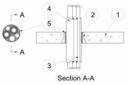
1.Floor Assembly — (Config A) Min 2-1/2 in. (64 mm) thick reinforced lightweight or normal weight (100-150 pcf or 1600-2400 kg/m3) concrete.
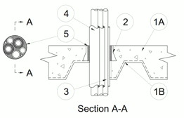
1A.Floor Assembly — (Config B) As an alternate to item 1. The fire-rated unprotected concrete and steel floor assembly shall be constructed of the materials and in the manner specified in the individual D900 Series designs in the UL Fire Resistance Directory and as summarized below:
A.Concrete — Min 2-1/2 in. (64 mm) thick reinforced lightweight or normal weight (100-150 pcf or 1600-2400 kg/m3) concrete.B.Steel Floor and Form Units* — Composite or non-composite max 3 in. (76 mm) deep fluted galv units as specified in the individual Floor-Ceiling design.The T Rating of the firestop system is 0 Hr for Config A, 1/4 Hr for Config B with nom 3 in. (76 mm) device or smaller (Item 2), and 1-1/4 Hr for Config B with nom 4 in. (102 mm) device (Item 2).
2.Firestop Device* — Cast in place firestop device permanently embedded during concrete placement in accordance with accompanying installation instructions. The device may be trimmed flush with the top surface or extend max 5-1/2 in. (140 mm) above top surface in min 2-1/2 in. (64 mm) floors. The devices are provided in nom 2, 3, and 4 in. (51, 76, and 102 mm) diam sizes.
RECTORSEAL — Metacaulk Cast -in- Place Device
3.Through Penetrants — Pipes, tubing or cable to be bundled within the opening. The space between penetrants and periphery of opening and annular space between penetrants shall be min 0 in. (point contact). Penetrants to be rigidly supported on both sides of floor assembly. The following types and sizes of penetrants may be used:
A.Metallic Pipes — A max of four pipes or tubes installed within opening. The following types and sizes of metallic pipes, conduits or tubing may be used:
1.Copper Tubing — Nom 1 in. (25 mm) diam (or smaller) Type L (or heavier) copper tubing.2.Copper Pipe — Nom 1 in. (25 mm) diam (or smaller) Regular (or heavier) copper pipe.B.Polyvinyl Chloride (PVC) Pipe — A max of one nom 1-1/4 in. (32 mm) diam (or smaller) Schedule 40 solid core PVC pipe for use in closed (process or supply) or vented (drain, waste or vent) piping systems.C.Cables — A max of two, max 8/C No. 18 AWG (or smaller) thermostat cables; XLPE or PVC insulation with XLPE or PVC jacket.
4.Tube Insulation-Plastics+ — Max 1 in. (25 mm) thick acrylonitrile butadiene/polyvinyl chloride (AB/PVC) flexible foam furnished in the form of tubing. Tubing may or may not be provided on all or any copper tubes or pipes.
See Plastics (QMFZ2) category in the Plastics Recognized Component Directory for names of manufacturers. Any Recognized Component tube insulation material meeting the above specifications and having a UL 94 Flammability Classification of 94-5A may be used.
5.Packing Material — Min 3 in. (76 mm) thickness of min 4 pcf (64 kg/m3) mineral wool batt insulation firmly packed into the annular space as a permanent form. The packing material is to be installed flush with the top surface of the floor.
6.Fill, Void or Cavity Material* — Caulk — (Optional, Not Shown) - Min 1/2 in. (13 mm) thickness. Caulk applied within device to finish flush with top surface of device.
RECTORSEAL — Metacaulk 150+ , Metacaulk 1000 or Metacaulk 1200W Rating applies only when packing material (Item 5) and (Item 6) sealant is used.